This is the first of two installments on AutoCAD Electrical Pin Lists.
AutoCAD Electrical tracks the assigned contacts for devices using a combination of Pin Lists fields in the catalog database Pin Lists tables. Catalog devices, such as relays, motor starters and connectors, come out-of-the-box with these Pin List fields predefined, but you can add efficiency and accuracy to your designs by adding Pin List information to any device in the catalog database. For instance, if you add Pin List information to a Limit Switch that has 2 Normally Open contacts, the software will automatically send an alert if you try to assign a Normally Closed Limit Switch to that particular catalog device. When connecting child objects AutoCAD Electrical will send an alert if the contacts exceed the predefined available contacts. You can also setup a Pin List sequence in order to default to the next available terminal pin numbers for each device. You may have already encountered this behavior when working with the aforementioned coils and a few other out-of-the-box devices.
Pins are associated with the manufacturer and catalog number of a device and applied when the catalog information is assigned. Any device can have pins assigned and are used for error checking as well as accurate, correct connections. There are four Pin Lists fields available for each device in the catalog determined by the type of device. In this first installment we will concentrate on the COILPINS and PINLIST fields and since Push Buttons do not contain pin information out-of-the-box, let’s start with them.
COILPINS & PINLIST
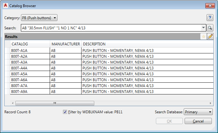
Using the Icon Menu, place a “Push Button NO” and in the “Insert / Edit Component” dialog box select Lookup. Next in the “Catalog Browser” dialog box, Search for AB "30.5mm FLUSH" "1 NO 1 NC" 4/13 which will produce a list of eight different colored 800T-A#A push buttons as seen in the image below.
In the upper right hand corner of the dialog box, edit the catalog database by selecting the pencil icon.  The catalog info should now have a yellow background revealing that you are now in Edit Mode. Move the slider bar all the way to the right so that you can see the four columns named COILPINS, PINLIST, PEERCOILPINS and PEERPINLIST. All four columns, which represent the four fields in the Pin List tables, have basically the same format. However, the two “PEER” columns are used when there are two parent devices, such as a forward and reversing motor starter or latching and unlatching relays. Since this does not apply to our push button, we will address the “PEER” fields in the second installment of this article (Part Two).
Both fields use the same format:
TYPE,TERM01,TERM02,TERM03,etc; TYPE,TERM01,TERM02,TERM03,etc
In a nutshell, the COILPINS field is for the parent component and the PINLIST field is for the child components. This means that when you assign the catalog information to a parent symbol it will pull the pin information from the COILPINS field. Likewise, when you relate a child component to a parent or sibling it will pull the pin information for the child component from the PINLIST field. Many times these two columns will contain the exact same information with possibly some minor differences. If there are no child components for a particular device, then you need to use the COILPINS field and leave the PINLIST field blank (case with a 1 NO push button). In our case, however, we have a 1 NO and 1 NC push button so we will use both fields.
 On the very top row, which is the 800T-A1A green push button, double click in the COILPINS field. If you know all the Type format codes you could manually enter the pins at this time but we are going to assume that you do not know the codes and select the Edit Coil Pins button, as seen in the image to the right.
Now we are in the “Coil Pins” dialog box. Under “Type” you have three options which have the following codes:
Undefined = 0
Normally Open = 1
Normally Closed = 2
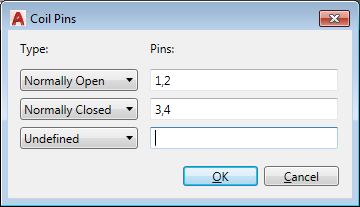
Our push button is 1 NO and 1 NC and the parent symbol could be either one. So for “Type” select Normally Open.
The pins will be assigned to the TERM## attributes in the sequence that they are entered. Each pin is separated by a comma. In the push button symbol there are two pins represented by the attributes TERM01 and TERM02 for pin 1 and pin 2 respectively which are entered here under “Pins” as 1,2. After entering this information another row appears in the dialog box. For this row select Normally Closed and set the pins as 3,4. We will not be using the third type so leave it as is and the Coil Pins dialog box should look like the image below.
Select OK and return to the “Catalog Browser – Edit Mode” dialog box. In the Catalog Browser you see the information using the codes listed above separated by a semicolon as: 1,1,2;2,3,4
One side note, if there is only one COILPINS setting and the type is set to “Undefined” the “0” code is unnecessary and automatically dropped. For instance, in a single pole circuit breaker, the COILPINS would be set to “1,2” and not “0,1,2”.
To set the child component in the PINLIST simply copy the COILPINS to the clipboard using CTRL-C and paste to the PINLIST using CTRL-V. In our case we want to attach a light as a child component so double click in the PINLIST field and select the Edit Coil Pins button. This time in the “Pin List” dialog box, since we copied the pins to start with, Normally Open and Normally Closed are already defined, but we now have some additional types available to us. These six options will produce the following types and codes:
| Normally Open = 1 | |||
| Normally Closed =2 | |||
| Form-C = 3 | NO/NC Pair | ||
| Convertible = 0 | The same pin numbers are used for all contacts | ||
| Undefined = 4 | or Multiple-Pole Terminal Strip | ||
| Stacked Terminal = 5 | or Multiple-Pin |
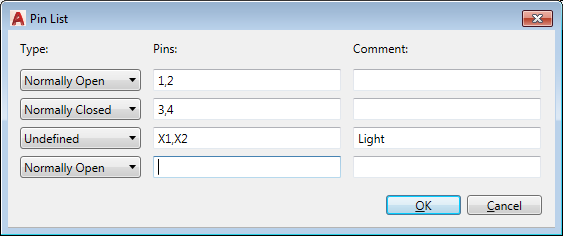
Note that under PINLIST 0 equals Convertible and 4 equals Undefined which is different than the COILPINS field, so keep that in mind when copying and pasting. For the light, set the third row to Undefined and the pins to X1,X2. Under “Comment” enter Light. The dialog box should now look like the image below.
Select OK and return to the “Catalog Browser – Edit Mode” dialog box. In the Catalog Browser you see the information using the codes listed above separated by a semicolon as: 1,1,2;2,3,4;4,X1,X2,*Light
You can add an optional description label or comment to the PINLIST field but not the COILPINS. When manually adding a label or comment, it must be the last element of the list and it must start with an asterisk (*) exactly as you see in this example. We will see where this applies later in this article.
As a side note, the format for Convertible pins (or contact type 0) for devices that are different for NO and NC based on the orientation of the device are defined using four pins. The first two entries after the Type are NO and the last two are NC.
Format: 0,PinNO,PinNO,PinNC,PinNC
The format for Form-C (or contact type 3) devices, must have three pins.
Format: 3,PinCommon,PinNO,PinNC
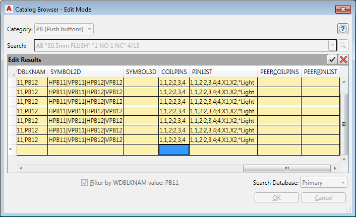
Back to our push buttons in the Catalog Browser; since the only difference in these eight push buttons are the colors, I want to set them all the same. Select the COILPINS on the row we just set and hold your SHIFT key down and select the PINLIST field on the same row. Copy this to your clipboard with a CTRL-C. Then select the COILPINS in the first row that has not been defined and hold your SHIFT key down selecting COILPINS in the last row that is not defined and paste using CTRL-V. Your Catalog Browser should now look like this:
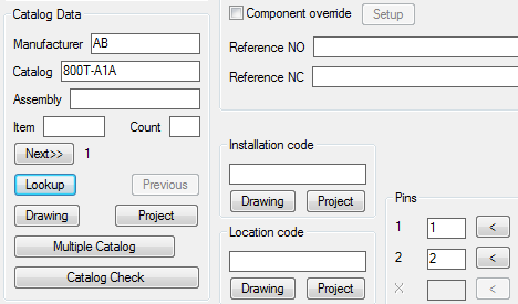
Select the “Accept Changes” button  in the upper right section of the dialog box. Now in the Catalog Browser, use the slider bar to return to the far left, select the 800T-A1A push button and click OK. Note that Pins 1 and 2 have now been assigned to the component in the “Insert / Edit Component” dialog box.
If you want to test this out further, place another push button from the Icon Menu, but this time use a “Push Button NC”. Lookup using the same search as before and pick any of the eight available. Once assigned, the normally closed push button will have pins 3 and 4 assigned to them.
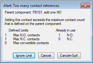
Next, let’s test the error checking. Using the Icon Menu, select a “2nd+ NO Contact” and place it in your drawing on a rung below the previous push button. In the “Insert / Edit Child Component” dialog box select the “Parent/Sibling” button and in the drawing select the previous push button. Immediately you receive a dialog box as pictured below, alerting you that there are “Too many contact references”. The parent component only has 1 NO contact and it is already in use.
Normally I would tell you not to use “Ignore Limit” because I think it is typically a bad idea. However, in this case I meant to put in a NC push button, so use Ignore Limit and we will fix it by toggling the push button to NC. You will get another dialog box warning that you have exceeded the maximum contact count for this component. Click OK. Back in the “Insert / Edit Child Component” you can see that the Child Component is attached to the Parent by way of the Cross Reference, but no pins have been assigned since we exceeded the limit. Select OK and return to the drawing.
On the Ribbon Menu > Schematic Tab > Edit Components Panel select the Toggle NO/NC Tool.  Next, select the child push button and toggle it to a NC Push Button. Notice that it assigned pins 3 and 4 to the NC push button as soon as it toggled. If you tried to assign another child NO or NC push button to the parent or sibling at this point, you would get another alert telling you that both contacts are already in use.
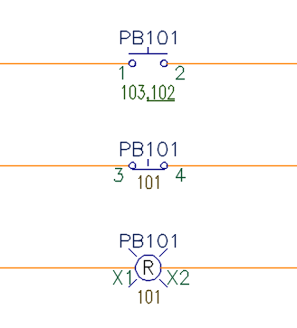
Let’s complete this task by adding the light. Using the Icon Menu under Push Buttons select and place a “2nd+ Red Light” on a rung below the previous push buttons. In the “Insert / Edit Child Component” dialog box select the “Parent/Sibling” button and in the drawing select either the parent or sibling push button. Note that Pin 1 is now set to X1 and Pin 2 is set to X2.
Before exiting the dialog box, take a quick side trip and click the “List” button below the pins. Note that in the “Pin Numbers in Use” dialog box in the bottom left under “Unused other (undefined)” the software lists Light=X1,X2 which corresponds with the label we entered into the PINLIST field. Select Cancel to return to the “Insert / Edit Child Component” dialog box.
Select OK to exit back to the drawing and it should look similar to the image below.
This is a new behavior with push buttons because they did not have pin assignments out-of-the-box. Now that these do, the software is automatically assigning the correct pins and performing live error checking as you work, but only for the catalog entries that we have assigned pins to. Unfortunately, this is not a global setting for all push buttons but then again pins are not assigned exactly the same for all push buttons.
Stay tuned for Part Two of “The Pin Is Mightier Than The Coil”, in which I will explain the PEERCOILPINS & PEERPINLIST fields.

Comments