
The mysteries of the Abydos hieroglyphs, is that a helicopter…or does it represent a type of soup?
|
Conspiracy theories aside, throughout time mankind has encountered symbols, languages and even artifacts…of which we have nearly no understanding. These mysteries have plagued scientists and theologians alike. A symbol’s meaning, it’s source, its usage… if we could unlock these mysteries what secrets of our own world might we learn?
 We’ll continue this effort by attempting to unlock a mysterious symbol within Autodesk® Inventor®. We know the symbol represents “adaptive”, but what does that mean? Why do we have it, what can it do for us?
All mysteries are meant to be solved and dealing with Autodesk Inventor icons/symbols is no exception. As we explore the meaning of Adaptive and what its purpose might be, we’ll learn:
- How it can be enabled
- How it speeds up the design process
- How it can be suppressed/turned off
- …and how it can be broken
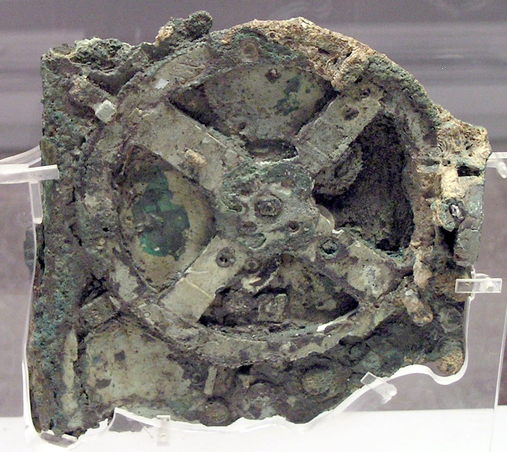
The Antikythera Mechanism. An ancient calendar or navigational device. Possibly the oldest hamster wheel? |
Ancient tools and techniques have been lost to the sands of time. So many items forgotten about…until they are uncovered. Only when we analyze the discovery do we begin to have more questions than answers. Okay, reality check… so the Adaptive symbol is not that mysterious. Within Autodesk Inventor, Adaptive functionality simply means “I am referencing something else from somewhere else” (that’s my layman’s description). A perfect example of this would be creating a mounting plate and you want the holes of the mounting plate to be correctly sized/located to match its mating component, like a basic I-beam, for example. Here’s what that looks like in steps and pictures. For the purposes of this article, we’ll only cover a simple cross-part adaptive association. Keep in mind, there are many objects and many different ways that components, sketches, surfaces, etc. can be adaptive or used as a reference for adaptive behavior. The following is only one of those many possibilities.
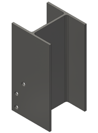 |
“Source” component: I-Beam with drilled holes |
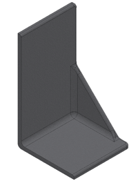 |
“Destination” component: Cast Iron mounting plate |
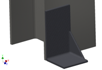 |
An assembly of the mounting plate, fixed/constrained on top of the I-Beam’s drilled holes. |
Step 1: From the assembly, edit the mounting plate by double-clicking on it.
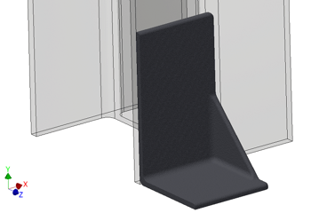 |
The I-Beam now appears transparent because you are editing the mounting plate part *through* the context of the assembly. Using this process allows you to see the other components so that you can either model around them, model with respect to them or use their geometry for adaptive referencing. |
Step 2: Create a 2D Sketch on the front (or back) face of the Mounting Plate
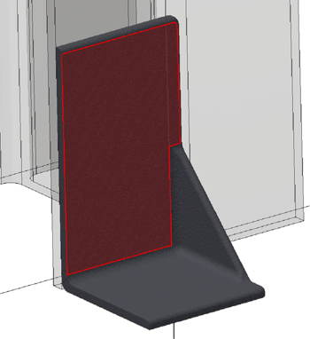 |
Remember, you are editing the Mounting Plate *through* the assembly. All edits are being done to the Mounting Plate.ipt file….**NOT** a copy. You are changing the original IPT model with any edits you make. |
Step 3: Rotate the view so that you can see the I-Beam drilled holes.
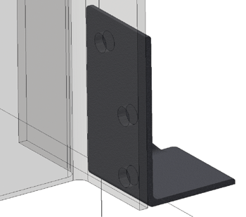 |
This allows you to see the geometry (drilled holes) for the next step. |
Step 4: Activate the “Project Geometry” command within the sketch environment.
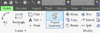 |
The “Project Geometry” command will only be available within the Sketch environment. This tool allows you to select source geometry and project copies to the active sketch. |
Step 5: With “Project Geometry” active, select 1 edge on each of the drilled holes in the I-Beam
 |
The “Project Geometry” command will remain active until you hit “ESC” or otherwise cancel the command. You can select edges or faces of any model and it will create sketch object copies of those objects within the active sketch. |
Note: Rotate the view around to see the front side of the sketch, notice the “yellow” reference objects
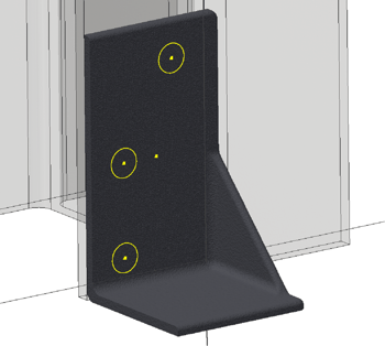 |
The “yellow” geometry may be another color. The color is determined by your Tools/Application Options/Colors tab/Color Scheme list. The objects could be purple, green, blue, etc. The important thing is that they are adaptive objects and do *NOT* require dimensioning. |
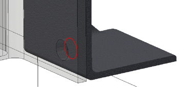
Note: In the browser tree, the sketch icon & mounting plate icon have changed.
 |
The red/blue(green maybe?) circle appears. This symbol represents Adaptive behavior. Notice the references listed underneath the sketch. |
Step 6: Finish the sketch and use the Extrude command to cut the holes using the projected circles.
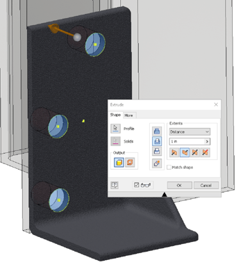 |
Now the newly extrude/cut holes in the Mounting Plate will exactly match the size and location of the holes drilled in the I-Beam. |
Here’s where Adaptive behavior pays off. If the holes in the I-Beam ever change location or size, they will automatically change in the Mounting Plate as well. This is what Adaptive referencing was built for. Adaptive behavior is a powerful tool, especially during the design phase when you aren’t sure how things are going to be sized, located, etc. Adaptive behavior allows you to link features within a sketch to other, source items so that when the source changes, the adaptive child items (such as sketch lines) change/update automatically.
Now for the downside to Adaptive behavior. When the design phase is complete, it’s always best to either disable the Adaptive reference (this functions as an on/off switch) or you can permanently break the link between the Adaptive reference and its source.
|
Adaptive On/Off Switch capability |
|
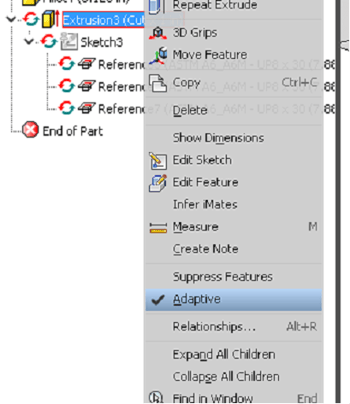 |
Right-click on the feature while editing the part, or on the part while in the top-level assembly… on the menu, there is an Adaptive option. The checkmark represents the On option …. unchecked is Off. |
|
Breaking the Adaptive reference |
|
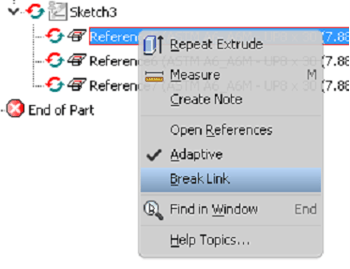 |
All adaptive references will be listed under the sketch. While “outside” of the sketch, right-click on a Reference and the menu will allow the ability to use the On/Off checkmark option …. or the “Break Link” option. The Break Link option is permanent and cannot be relinked (without an immediate Undo). This converts the projected/adaptive sketch geometry into standard sketch geometry. No changes to the source part/feature will update adaptive links that have been broken. |
Ah….mystery solved… sort of. As I said, there are a lot of uses and workflows for Adaptive behavior. We only scratched the surface of the workflow and possibilities for most average users. Inventor is a large and complicated piece of software, with many hidden abilities that take users years to discover. Hopefully, we’ve helped you uncover a tool/workflow that could shave time off your designs and improve your workflow and utilization of Inventor’s power. Now it’s back to uncovering the mysteries of the world around us. Uh Oh! My foil hat has a hole in it…..oh… not good, NOT GOOD!!!!


Comments