With 2019.1 and beyond, the Inventor Nesting tool can now interact with many new objects, beyond just Sheet metal components. Standard Part files can now be loaded into the nesting interface as well as Neutral format files (STL, STEP, etc.) that have planar faces, as well as composites that have a planar face.
With that in mind, there are situations where the shape generated within the Nesting environment doesn’t match the needs for the nest. In one example, the part was extruded “long-ways” as opposed to “face-ways”, so the base extrusion was in the wrong alignment to the nest. In another instance, I created a base extrusion and then immediately used the Mirror command to create a symmetric part. In this instance, the shape of the nested part was only half of the shape, as opposed to the whole thing, which obviously was not helpful.
In any of these situations, the fix is quite easy to accomplish.
First, open the part in question. In this case I have a part with a “U” shaped profile that was rather complicated and decided to create a symmetric Mirror as opposed to trying to sketch it all out in one shape.
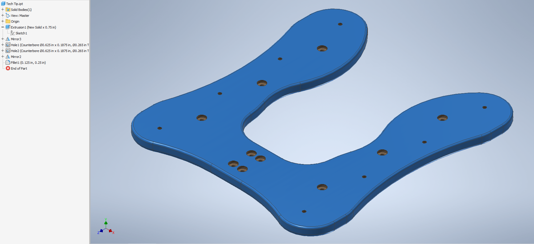
Note the Mirrors in the model browser.
This creates the right half of the U profile, as well as the right Hole patterns.
Now that I have the part open, I create a sketch on the matching origin plane to the one in question. I don’t want the inside of the U shape to be considered open space for the nest, so I will be particular in the sketch definition:
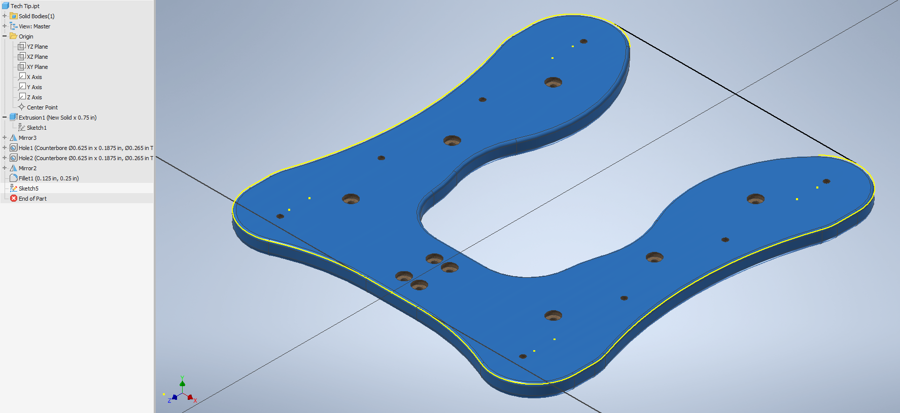
In this case, I used the project geometry tool as well as drew a single line across the top of the model to close off the inside area. Your sketch can be any shape as you see fit.
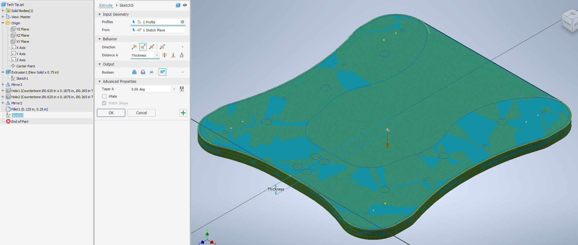
The next step is important, but easy-start an extrusion. I set up a parameter for thickness in the model to start and I used that in the extrusion depth, set the direction to match the direction of the original part, and lastly (and most importantly) set the output to new solid:
Now that the extrusion is created, right-click on it and choose Use for Nesting. This will allow the Nesting tool to use that profile for the nest creation.
The last thing to do is expand the Solid Bodies folder and rename the new solid, as well as turn off the visibility so it doesn’t interfere with another usage of the part.
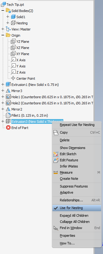
Note that with the option for Use for Nesting, the Solid, which has been renamed, as well as its visibility turned off
And that’s it! Once you have loaded this model in as a source in the nesting environment, the extrusion profile will be used automatically.
In doing some testing for this tech tip, I also created just a single sketch, and nothing else within a part file, and was able to nest the sketch.

Comments