Hagerman & Company recently received a support case from a client who wanted to access Revision Information in the Data Manager in order to export and import the info to Excel for processing. The customer was currently using Drawing Properties to track revisions, but these properties cannot be edited in the Data Manager. This method also meant that each drawing would need the revision info entered one drawing at a time which can be time consuming in a large project.
I felt this would be a great opportunity to share how to utilize the Annotation Class within Project Settings to add custom data to P&ID drawings that are not attached to specific pieces of equipment or components within the project itself. In order to do, I will use the Revision Block example that was addressed in the support case above.
PLEASE NOTE: Annotation Classes are only available in AutoCAD® P&ID. At this time there is not an equivalent method within AutoCAD® Plant 3D. For Plant 3D I would suggest using Vault.
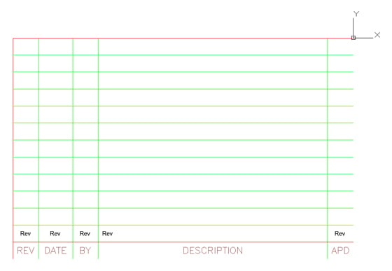
For this method, choose an AutoCAD Block saved in another drawing that you intend to use as the Annotation Symbol. Below is the block I will use, which matches up to the Title Block. The insertion point (where the UCS Icon is located) is the upper left corner of my Title Block. The column headers (REV, DATE, BY, DESCRIPTION and APD) were created with Single Line Text while the other five pieces of data are Attribute Definitions with a Tag of “Rev”. The attributes have no prompt, nor do they have a default value. They are simply place holders with the height, justification and layer that I want to utilize in my symbol.
Since these attributes will be defined when we create the symbol later, there is no need to copy them to every row at this time. I named my block “Revision Block P&ID” and inserted it into a drawing named “Rev Block.dwg” for access in the Project Setup. There is no magic in the names that I have used and at this point everything is plain vanilla AutoCAD block with attributes inside a plain drawing.
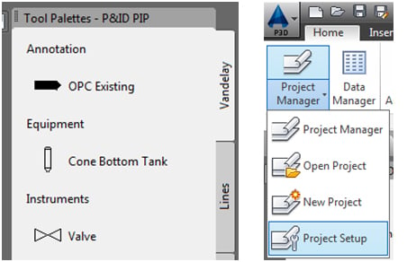
In order to access the symbol when I’m done, I’m going to put it in a Tool Palette. I will set my Active Tool Palette first. I like to keep my customized palette separate, so here I have named and activated my custom palette “Vandelay” (my “company name”). Next I will find the Home tab and select the Project Manage drop-down. From there, I will select Project Setup, which will lead me to my Project Settings.
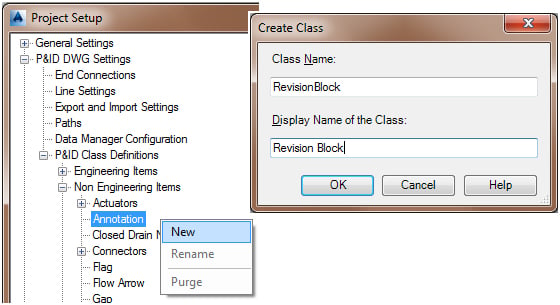
In the Project Setup dialogue box tree, Locate P&ID DWG Settings > P&ID Class Definitions > Non Engineering Items > Annotation then Right Click on Annotation and Click New. In the Create Class dialogue box, set the Class Name to RevisionBlock and the Display Name of the Class to Revision Block. The Class Name cannot include any spaces but the Display Name can. Click OK when finished.
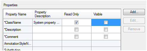
In the Properties section of the dialogue box (which I have condensed for clarity), I have turned off the Visibility of the ClassName, Description and Comment because I don’t want the end user to waste time pondering these or filling out a comment that is not being used. It is your descision as to whether you do this or not. Next you will click the Add button.
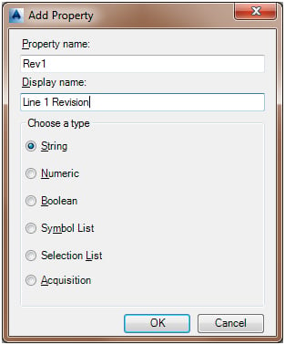
In the Add Property dialogue box, I set the Property Name to Rev1 and the Display Name to Line 1 Revision. Under “Choose a type”, select String and click OK to add the property to your project.
RINSE AND REPEAT
Continue to Add the following Properties for the five columns of Line 1. All Property Types are String.
Property Name Display Name
RevDate1 Line 1 Date
RevBy1 Line 1 Revised By
RevDesc1 Line 1 Description
RevAppd1 Line 1 Approved By
Click Apply To Save Your Work.
How many times you have to repeat this process will be determined by how many rows you have in your Revision Block. I have 12 rows in my revision block. As a result, there are a couple of rules I personally like to follow in order to simplify this as much as possible.
- You can name these properties however you like, but I recommend keeping it simple so that you can copy and paste as much as possible. You cannot copy and paste properties but you can copy and paste the text you type.
- You want to Add these properties in the order that you want them to appear in the Properties Palette as well as the Data Manager. You can’t move them around after the fact and you can’t rename them later so don’t take shortcuts. Put in all the Rev1, Rev2, Rev3, etc and then all the RevDate1, RevDate2, RevDate3, etc. Shortcuts can come back to haunt you, so take the extra time to create them in the sequence that will benefit the end user.
- Click Apply often –there is nothing worse than hitting that ESC key and having to do it over again.
- Set the Default Value for every single Property that you Add (from Rev1 to RevAppd12 in my example) to a SPACEBAR. Otherwise, everywhere you reference an empty property the attribute will contain a dot.
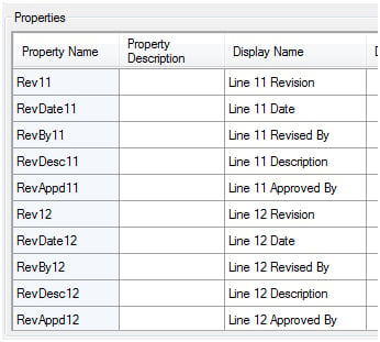
To simplify this for each row, click and highlight the Property Name for Rev1 and select CTRL-C. Then select Add and Paste (CTRL-V) the Property Name into the dialogue box, backspace over the 1 and change it to Rev2. I do not change the Display Name at this time but Click OK. Next, select the Display Name for Line 1 Revision, Copy and Paste over the Display Name for Rev2 and change it to Line 2 Revision. I repeated for RevDate2, RevBy2, RevDesc2, RevAppd2, Rev3 – fifty five times to be exact. While tedious, using this Copy & Paste method took less than 10 minutes ad kept everything in sequence all the way thru Rev12 as pictured below.
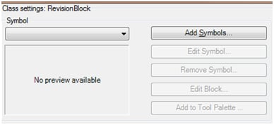
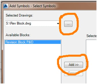
Now we need to add the Symbol to the project, so click on Add Symbols. In the Add Symbols – Select Symbols dialogue box, choose Browse and locate the drawing that contains your Revision Block. As stated in the beginning, my drawing is named “Rev Block.dwg” and under Available Blocks I select “Revision Block P&ID” and click Add >> to transfer the block in to Selected Blocks. At the bottom of the dialogue box click Next >>.
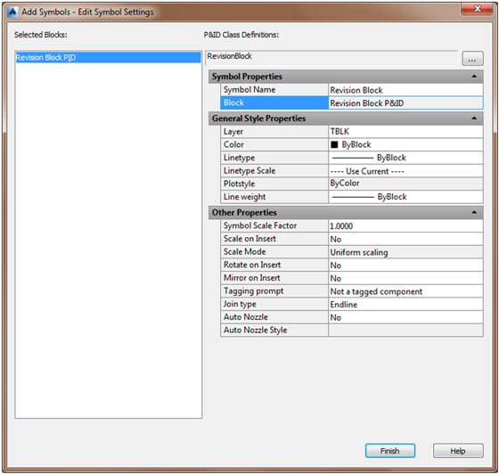
In the Add Symbols – Edit Symbol Settings dialogue box, set the following:
Symbol Name: Revision Block
Layer: Any Layer You Choose To Use
Color: ByBlock
Linetype: ByBlock
Line weight: ByBlock
Tagging prompt: Not a tagged component
Join type: Endline
Set any other properties as desired or as they appear in the image below, then in the bottom right click Finish.
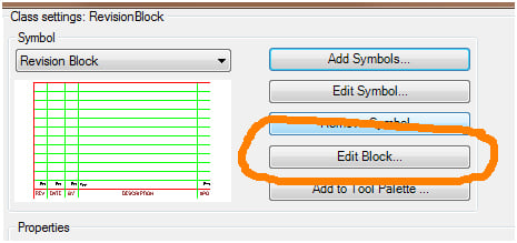
Now we are ready to set up our Block. Click Edit Block.
In the Block Editor, choose the Assign Format tool and select the first attribute tagged as “Rev”.

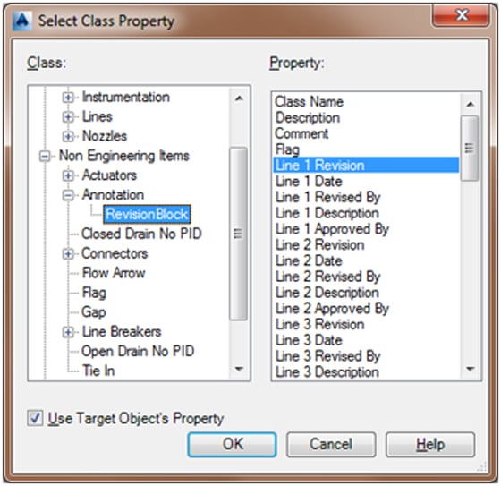
In the Assign Annotation Format dialogue box, click the Select Class Properties button. Now in the Select Class Property dialogue box with Use Targe Object’s Property activated, locate in the Class Tree Non Engineering Items > Annotation > Revision Block and for the Property select Line 1 Revision and click OK.
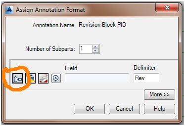
Back in the Assign Annotation Format dialogue box, make sure to blank out the Delimeter and then click OK.
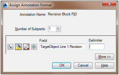
Trick: Once you start assigning the formats, if your columns are thin like mine, the attribute tags start overlapping making it hard to see. I simply make the attribute definition height temporarily smaller so that I can see which one is which until I finish them all and then change them back to the correct height. Finish setting the remaining attribute definitions for Line 1. Always remember to remove any text from the Delimeter field. Don’t be surprised that after you hit OK the the Attribute Tag will read with the actual Class Name instead of the Display Name – this is normal.
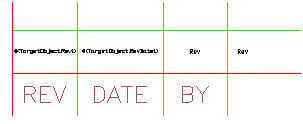
DATE = TargetObject.Line 1 Date
BY = TargetObject.Line 1 Revised By
DESCRIPTION = TargetObject.Line 1 Description
APD = TargetObject.Line 1 Approved By
After the entire row of Attribute Definitions have been assigned their Properties, using AutoCAD’s Copy command, copy all attributes on Row 1 to Row 2 thru 12. As I stated in my personal rules previously, using a simple class name can help to alleviate the pain of going through this process repeatedly. I do not recommend this trick when Assigning a Format to a new attribute, however, when editing similar formats, it will come in quite handy.
Next, open up the Properties Palette and select the copied attribute in the REV column for Row 2. In the Properties palette under Text, locate the Tag. DO NOT try to retype the entire Tag, but simply change the “1” to “2” so that it now reads #(TargetObject.Rev2). It is vital that you then click out of the Tag into another field like Prompt so that the change you made will stick. Then hit ESC to clear your selection and move onto the next one. If you used the same naming convention that I have, you should be able to change 55 attribute tags from 1 to 2 thru 12 for every row in record time.
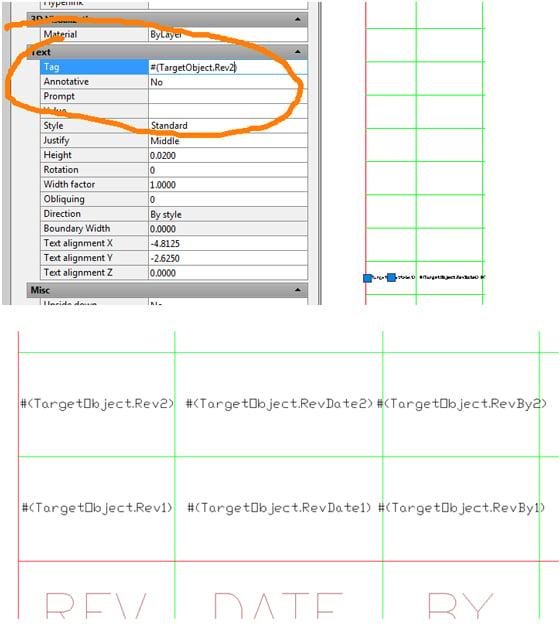
For those of you who did not keep it simple, you might find your only choice is to use the Assign Format button 55 times. If that is the case you should continue this article after lunch because the rest of us will be done in a few minutes.
“DANGER, WILL ROBINSON"
DO NOT double click the attribute tags and try to change the 1 to a 2 in the Edit Attribute Definition dialogue box. You will get incorrect and unpredictable results. This AutoCAD dialogue box will change the case and delete unwanted characters and all sorts of things that you do not want it to do. So no double clicking, and no dialouge box. Make the above change either in the Properties Palette OR use the Assign Format Tool.
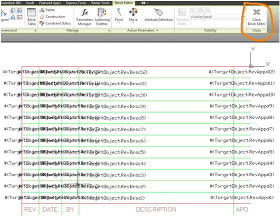
If you changed the height of the attribute definitions as I did earlier, now is the time to change the height back for the final symbol. Don’t worry about the overlap of the tags, as seen below, for what you input normally will not be as many characters as these tags. Once you are happy with your symbol, click on Close Block Editor to return to the Project Settings.
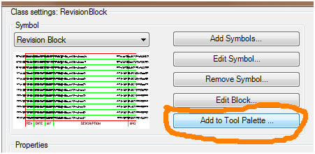
The last step is to click Add to Tool Palette and then click OK to apply your changes and exit Project Settings, thus returning to your P&ID Drawing.
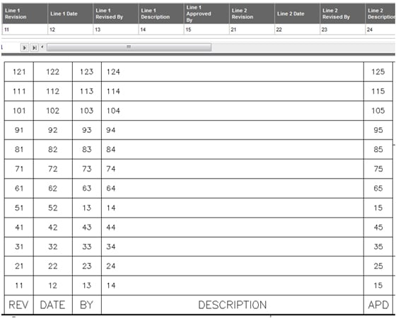
From the Tool Palette, you can add Revision Block or any other type of Annotation to your drawings. Before adding this new symbol into multiple drawings though, I highly suggest testing it to make sure everything is defined correctly. Check by entering unique text into each properties in the Data Manager and confirm they appear in the correct spots of the revision block. Below you will see that in Row 5 I missed changing three Tags. Fixing this error before placing it in hundreds of drawings wil be a big time saver in itself.
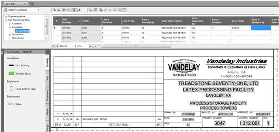
Once it has been added to various drawings in the project, you can access all of the Property sets in the Data Manager or in the Properties Palette (not pictured). You will have the capability to edit, copy and paste in the Data Manager exactly as you would with any other component in the project as well as exporting to Excel, making changes and importing these changes back in for Acceptance in the Data Manager.
Note: Just like any other component in a project, you cannot transfer Class Definitions and Project Properties from one Project to another. As a result, to utilize this method in existing projects, you would need to add this annotation to each and every individual existing project.
New Projects will be able to inherit these definitions and properties via the “Copy Settings from existing project” just like any other setting. This method offers a faster, easier and more accurate method for adding and editing Revision Information or any other type of annotation you create for your project, no matter how large or small.


Comments