There are cases when design intent is better shown in 3D, rather than the conventional live section cut through a portion of a floor plan. Sometimes there are elements just behind or in front of the cut plane that interact with the elements shown in a traditional 2D section.
Autodesk® Revit® has a section box tool that allows you to stretch and collapse four cut planes in the form of a box that will isolate smaller portions of the model. Users may turn the section box visibility and the provided blue arrow grips on to easily manipulate the edges of the box to create the desired shape.
While this is a powerful tool for visualization, manipulating the box to the desired rotation, cropping and naming the view and setting it as your 3D Isometric view can take some time. After all of this, you still must stretch the section box back out in the default 3D view and do the same process over again for the next area you want to isolate.
In this article, I will show you a quick way to get the portion of the building isolated with the click of a button and vastly reduce the time it takes to make a 3D Isometric section.
First, you need to have a wall or building section in a plan view. In this example I will use an exterior wall section of a model.
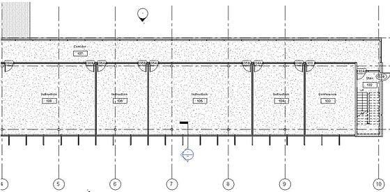
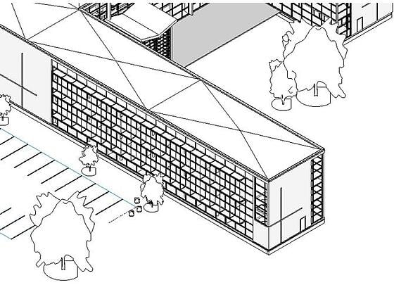
After the section has been placed,take a look at the default 3D view.
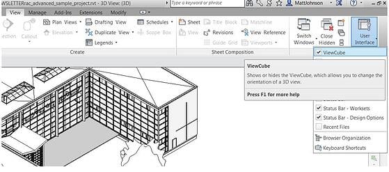
In the 3D view drawing area, the view cube needs to be displayed. If the view cube is not displayed you may toggle it on by going to the view tab and hitting the user interface button to check the box “view cube” to display it.
Once the view cube is displayed, you can right click on it and choose orient to view. In “Sections”, select 3D isometric view. In this example I named the wall section “3d”.
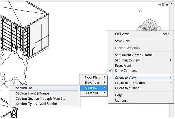
The view will then orient to the section in a perpendicular view point. You can rotate the 3d view to your desired aspect.
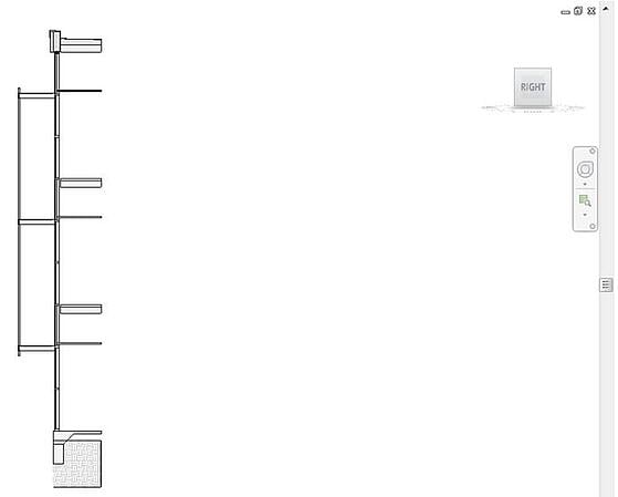
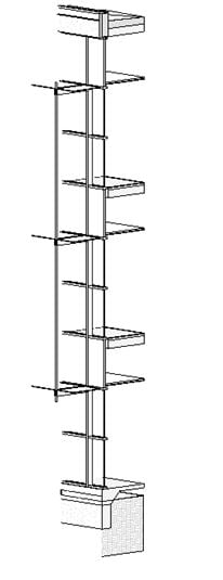
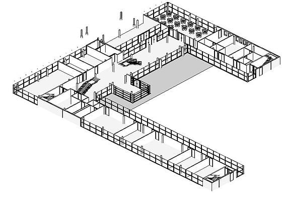
In the project browser you can then right click and rename the isometric 3D view and it can then be applied to a sheet. To repeat, you can return back to the default 3D view and do this for as many sections or plan views as you like. Here is an example of orienting the view to a floor plan.


Comments