I recently did a search for “Autodesk Inventor Tips”. As you can imagine there were lots of results. Many of the tips were very good. But there were just as many, if not more, that I knew I really wasn’t going to use.
Most of the tips listed here are ones that you can just “turn on”, put in your template, or setup once and forget about them.
In no particular order, here are my 9 Inventor tips you should start using immediately:
1- Quick Access Toolbar (QAT)
Add your frequently used commands to the Quick Access Toolbar. The QAT is now in every windows application, so you can use this tip for all of them. The QAT is the toolbar that is by default located at the top of your application window, above your ribbon. (You can move the QAT to below the ribbon also.) You have two options for adding commands to the QAT. The first is clicking on the pull down menu then selecting the command. I recommend at least adding “iProperties”.
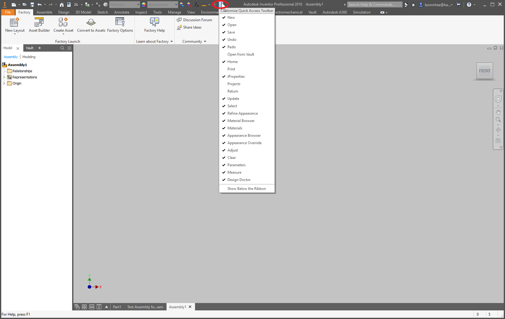
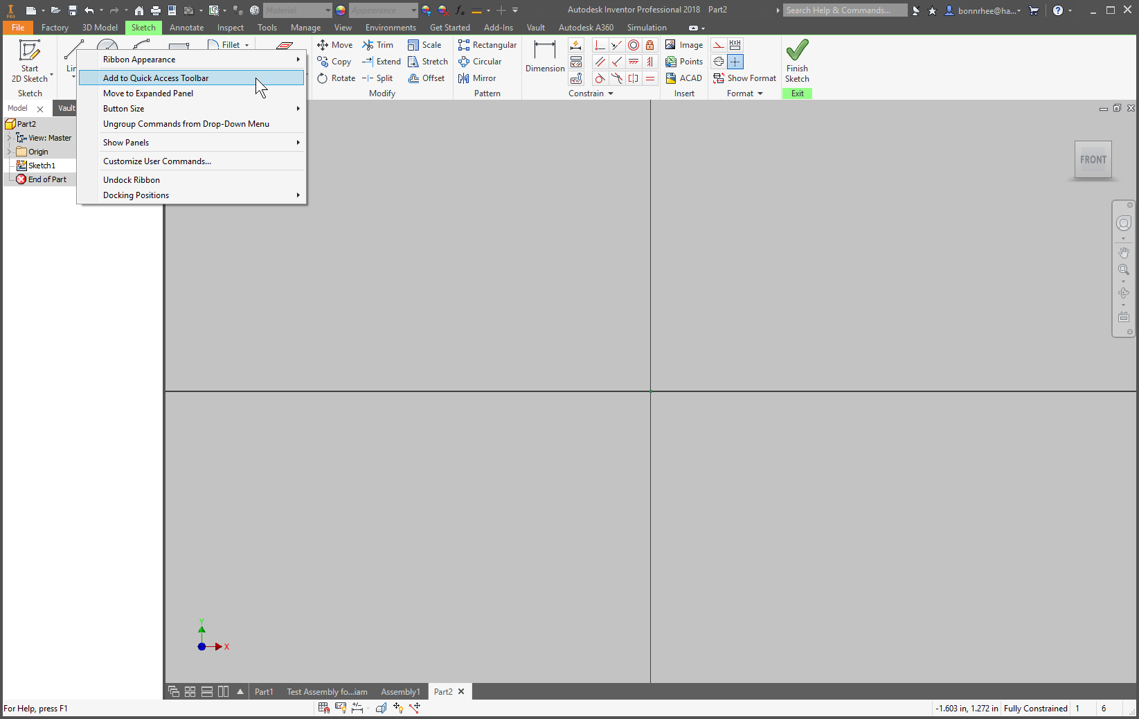
The second option is to right click on a command and then select “Add to Quick Access Toolbar” from the menu.
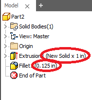
2- Display Extended Information
This option will show you extra detail about the feature you wouldn’t normally see in the Inventor browser! In my screenshot below, you can see “(New Solid x 1in)” and “(0.125in)”. These tell me the depth of my extrusion and the size of my fillet.
Access: TOOLS (tab) – OPTIONS (panel) - APPLICATION OPTIONS (command) – PART (tab)
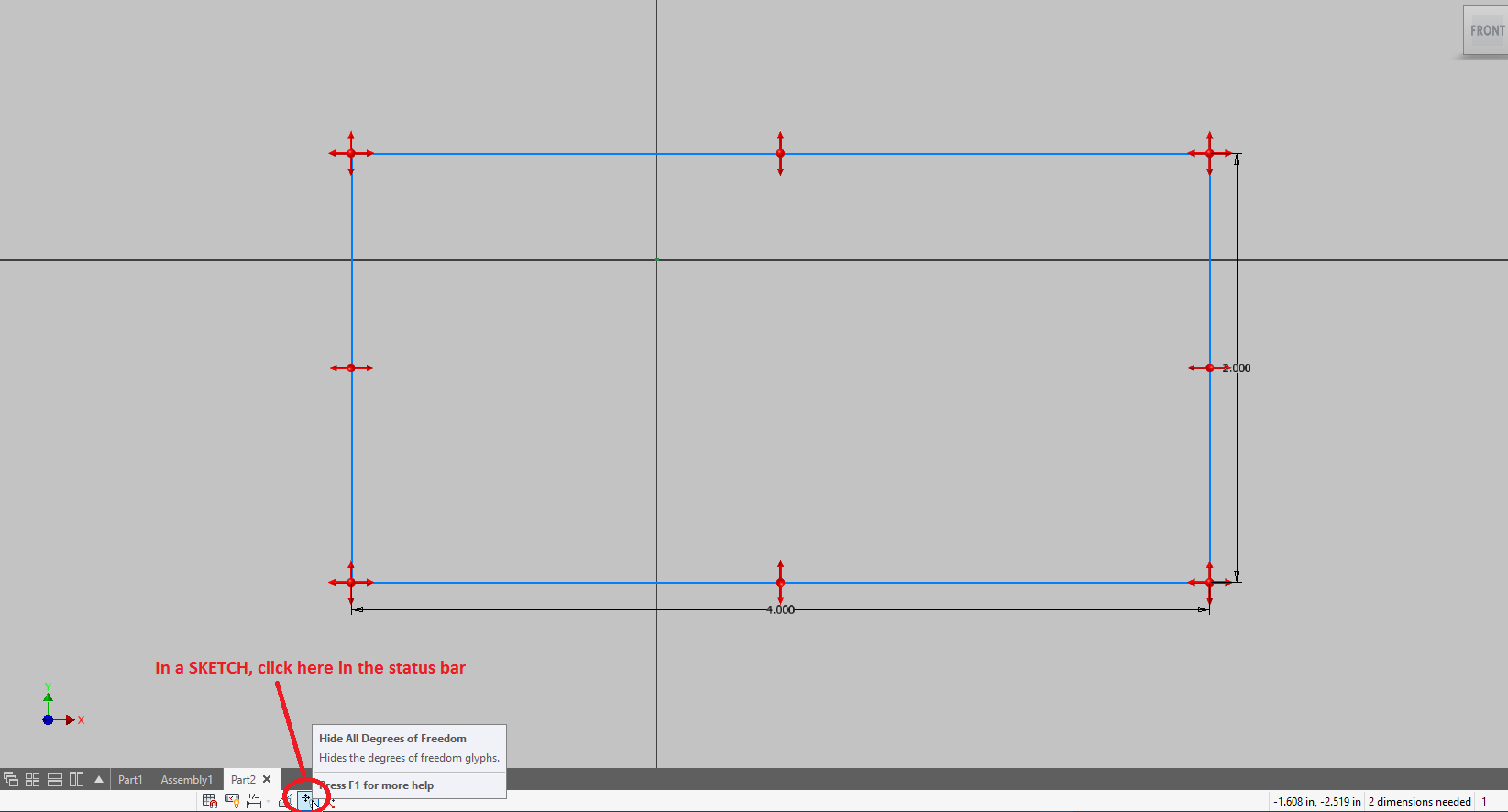
3- Display Degrees of Freedom (Parts)
A good practice is to always fully constrain your sketches. But in more complicated sketches, it’s hard to find which dimensions or constraints you need to constrain your geometry. If you are ever in this situation, go into the sketch and you can toggle your degrees of freedom by clicking on the icon in the status bar. In my screenshot, you can see the red arrows indicating the degrees of freedom in my sketch. The lines are dimensioned, but they are still “floating” in the X and Y direction. Click again to hide the degrees of freedom.
Access: In a SKETCH – click on the icon in the STATUS BAR
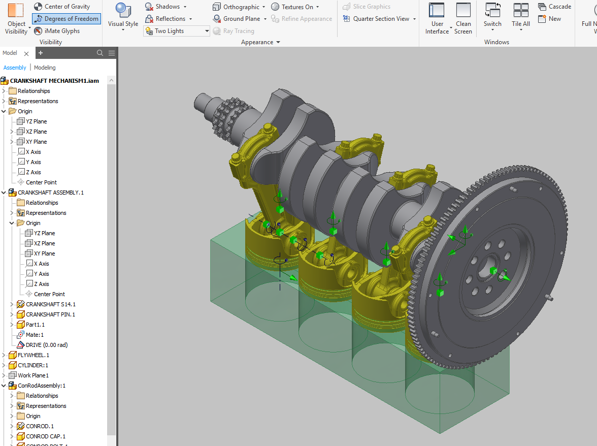
4- Display Degrees of Freedom (Assemblies)
Similar to the previous tip, you should (almost) always full constrain your assemblies. (An exception might by something like a screw or bolt.) If you turn this option on, you will see green arrows indicating the degrees of freedom for a component.
Access: In an ASSEMBLY - VIEW (tab) – VISIBILITY (panel) – DEGREES OF FREEDOM
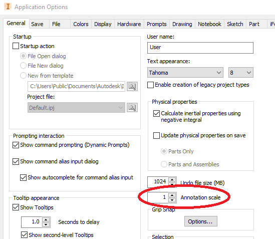
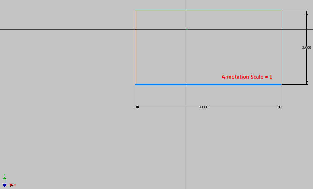
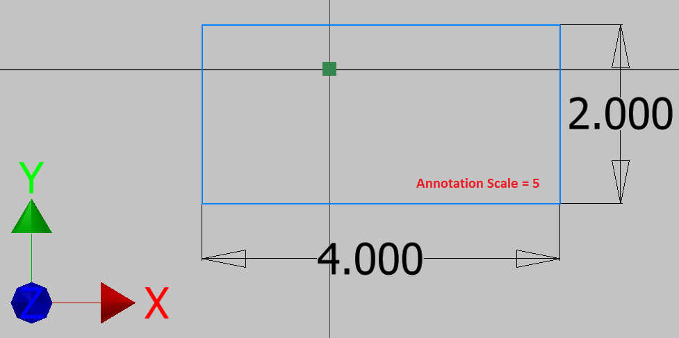
5 – Annotation Scale
I am not getting any younger so my eyes deteriorate just a little every day. Hopefully your vision is better than mine. If not, you may want to use a larger Annotation Scale in Inventor. This sets the size of dimension text, arrowheads and other symbols. The default value is 1, but the scale can be set from 0.2 to 5.0. Look how big the dimensions and the UCS are when the scale is set to 5!! It makes me feel like I am using binoculars!
Access: TOOLS (tab) – OPTIONS (panel) - APPLICATION OPTIONS (command) – GENERAL (tab) – Annotation Scale
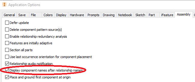
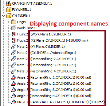
6 – Component Names After Relationship Names
This option will display the components that are related to a constraint! You can also right click on a constraint and select “Other half”…but I like the extra information I see with this option.
Access: TOOLS (tab) – OPTIONS (panel) - APPLICATION OPTIONS (command) – ASSEMBLY (tab)
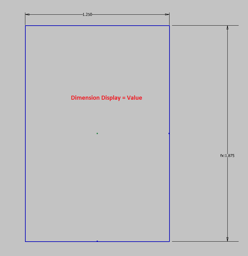
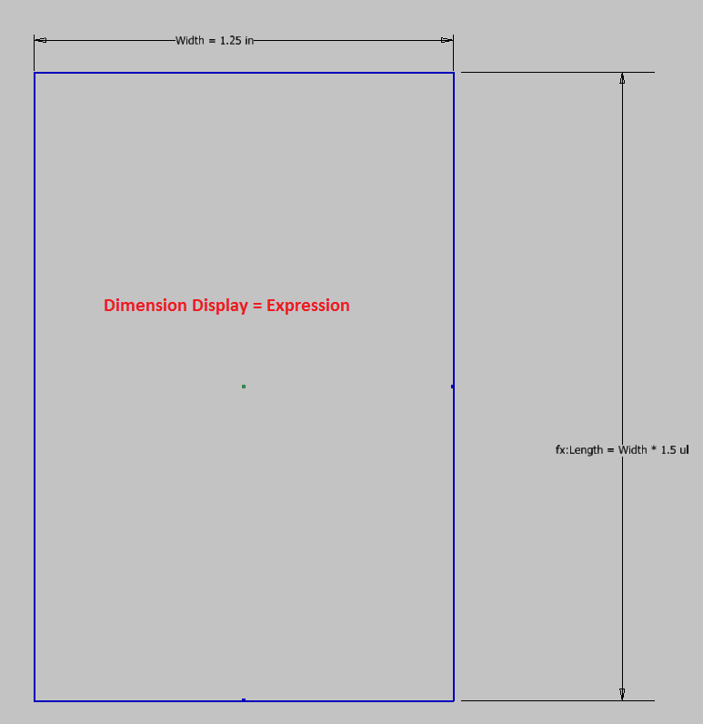
7 – Dimension Display
By default Inventor displays the value only for dimensions. If you are getting the most out of parameters in Inventor, there will be occasions when you will need to see more than just the value of a dimension. What if there is a relationship with another dimension? How do you know without looking at the “FX” table or editing the dimension? Well, turn on Dimension Display! I like to see “Expression” by default, so I changed this in my template.
Access: Part file – Right Click – DIMENSION DISPLAY – select (VALUE, NAME, EXPRESSION, TOLERANCE, PRECISE VALUE)
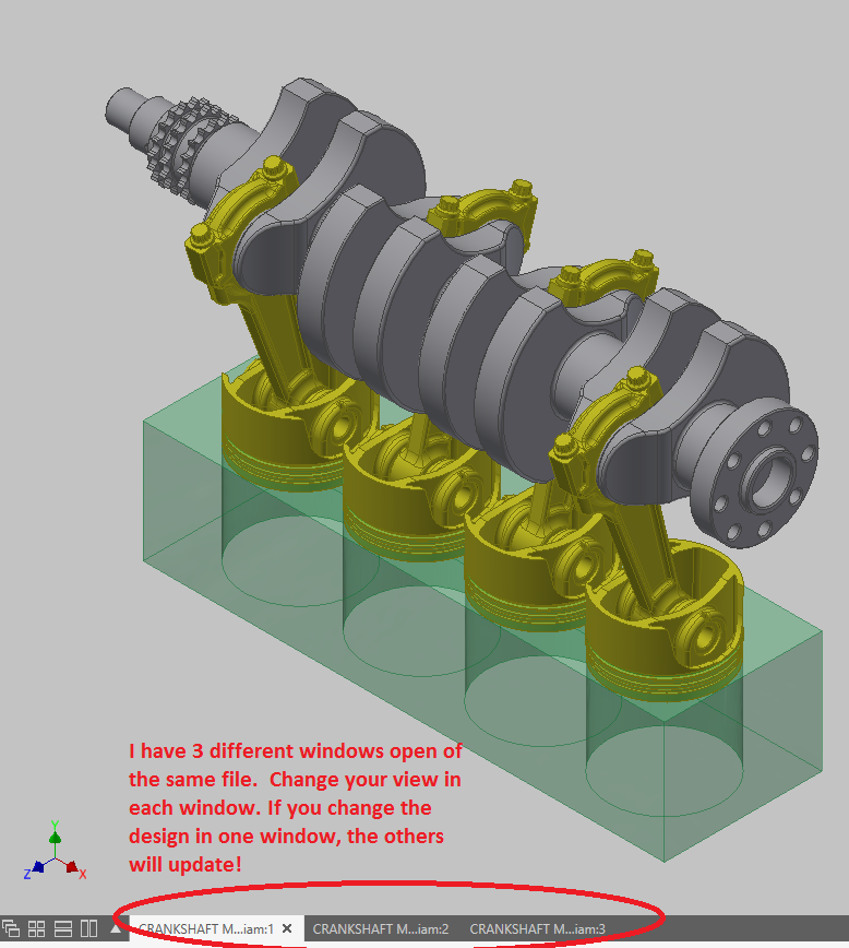
8 – New Window
Have you ever been working on a model and you are constantly changing, rotating and orbiting your view? Well you have 2 options to be more productive. The first is creating a VIEW REPRESENATION, which is a discussion for another time. But for this tip, try creating a new window, each with a unique view. You can create a new window of your file without actually OPENING another session of the file. IE, you will only have 1 file open. If you happen to change the design in one window, the other windows will update!
Access: VIEW (tab) – WINDOWS (panel) – NEW
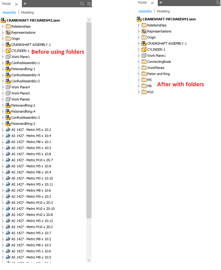
9 – Folders in the Assembly Browser
Do your assemblies have many of the same components? Do you find it hard to navigate your assembly browser? Are you constantly scrolling in the assembly browser? Look at the below and after screenshots! Take it a step further and create folders like “Nuts”, “Bolts”, “Fittings” in your assembly templates then everyone will be using “standard” assembly folders!
Access: Assembly Browser – Right click on component(s) – select ADD TO NEW FOLDER (rename) – (drag and drop other components into the folder as needed)
.jpg?width=200&height=200&name=Bonn%20Rhee%20(300).jpg)
Comments