As Controls Engineers, we are all aware that design involves both hardware and software, typically including PLC logic. The hardware design explains the physical wiring and descriptions, and the software design makes it happen. Sometimes one engineer or designer does the hardware design, and another does the software (PLC/HMI/etc.).
Hardware and software engineers need to collaborate just as Controls and Mechanical engineers do. Commonly, the software is produced before the hardware design, and we need to ensure that they are communicating and working off the "same page."
AutoCAD® Electrical has a utility that allows the PLC I/O design to happen via a spreadsheet and then imported to create the drawings, including ladders, I/O module address, and descriptions. It also understands the terminals connected to each I/O point.
Once the drawings have been created, AutoCAD Electrical has a report that allows the export of I/O addresses and descriptions to be imported directly into the PLC program. It is helpful not to have to "fat finger" the same information in multiple programs. Therefore, if you made a mistake in a description field, it will at least be consistent. (I know, that never happens!)
Below is a typical spreadsheet that depicts the I/O module and points.
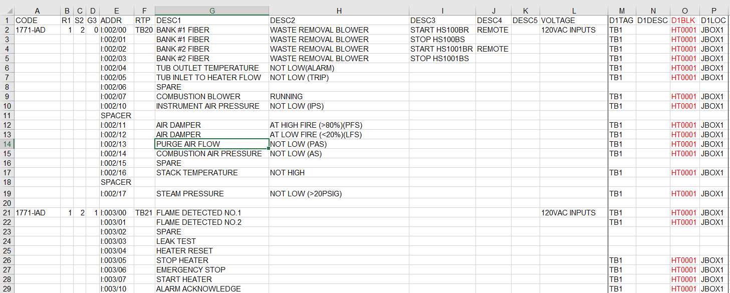
The spreadsheet contains all of the information necessary to create the hardware drawings. It may seem like a lot of information, but there are templates available to start, and once you have created your first spreadsheet, it can be used again for different projects. The old saying "never create what you can 'steal'" is appropriate in this situation. Much like you save circuits in AutoCAD Electrical, the same concept applies.
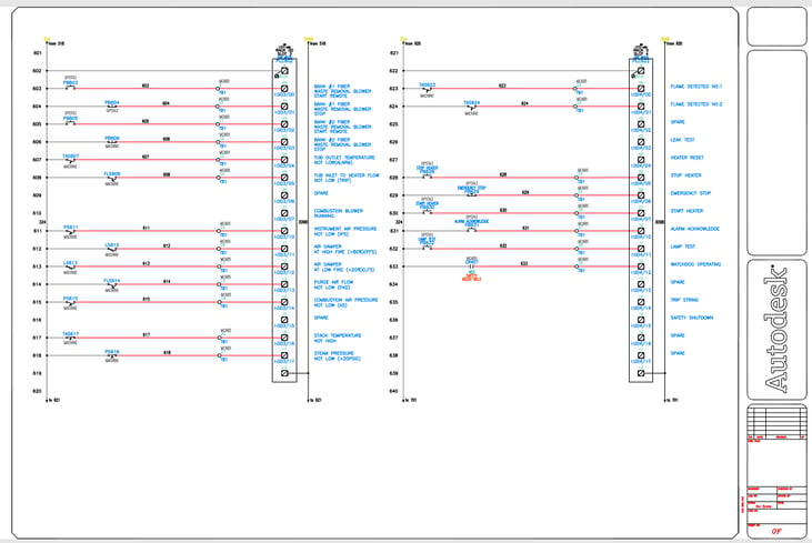
By defining all of the necessary information in the spreadsheet, the drawing above is created.
I wish there were a magic button to allow all of this to work, but there isn't. The spreadsheet needs to be set up with all of the utility's information to create the drawing. The drawing templates, symbols, etc., need to be created before the utility. The first time is not going to save you hours. In fact, it might take time, and a few tries to get the desired results, but once you work through creating and debugging this process, you will save time in the future—both in drawing creation time as well as consistency of data.
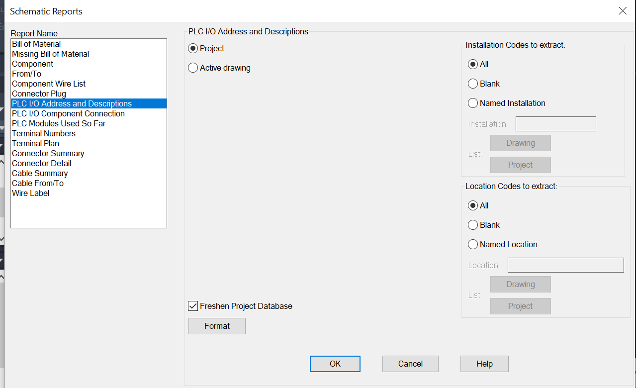
Now, how do we complete the loop on the PLC logic? Like everything in AutoCAD Electrical, there is a report to handle that. Within the Schematic Reports, you choose "PLC I/O Addresses and Descriptions." From here, you may choose to export the current drawing or the entire project. That's up to your workflow and process. Keep in mind that you do not need to use the Spreadsheet to DWG utility to run this report. In fact, many customers start with the hardware design in AutoCAD Electrical and utilize this report to import into your PLC program, which saves time and provides consistency.
Whether you want to start with a spreadsheet and then create drawings or create the I/O drawings and export them to the PLC program is up to you. Hagerman offers workshops and service offerings to assist you in understanding the workflow, creating the Excel templates, and setting up AutoCAD Electrical to import that data to create the I/O drawings and understanding the I/O to PLC export report.
|
|


Comments