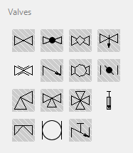
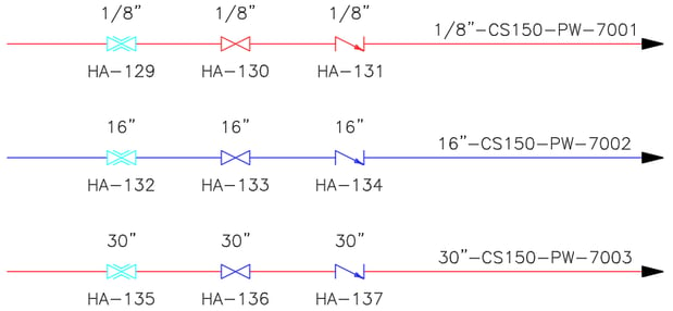
At the end of my last article, “AutoCAD® Plant 3D and P&ID 2017.1 & 2018 - Spec Driven P&ID Project”, I mentioned that I would next tackle the addition of Pinch, Knife and Rotary Valves to both the P&ID Pipe Spec Object Mapping and the Plant 3D P&ID Object Mapping. In case you do not recall, the reason we need to cover this for the P&ID Spec Driven Project is because those valves are on the tool palette but as seen in this image they do not have a background hatch. If you look back at the previous article, in the Project Settings, I pointed out that the pinch valve was displayed in grey text because it had not been mapped. The same is true for the knife and rotary valves. Since they have not been mapped, the spec verification ignores these components and treats them no different than it would equipment, instrumentation or other components that are not in your specifications.
 In this article I will show how you can add these valves to the Pipe Spec Object Mapping which will require some changes to one of the project XML files. While we are at it, these same three valves are also not available on the Plant 3D side in the Plant 3D Class Mapping, so why not kill two birds with one stone?
Just for the record, no birds were harmed in the writing of this article.
P&ID Pipe Spec Object Mapping
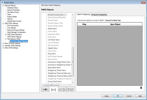
![]() First we will take care of the Pipe Spec Object Mapping on the P&ID side of the software. In the Project Setup, select P&ID DWG Settings > Pipe Specs in P&ID > Pipe Spec Object Mapping then select the icon for the valves. As in the image below, many of the objects are already matched and are displayed in black text. Components displayed in grey text have not been mapped. Note that the Globe Valve and Needle Valve have been mapped but the Knife, Pinch and Rotary Valves have not been mapped.
First we will take care of the Pipe Spec Object Mapping on the P&ID side of the software. In the Project Setup, select P&ID DWG Settings > Pipe Specs in P&ID > Pipe Spec Object Mapping then select the icon for the valves. As in the image below, many of the objects are already matched and are displayed in black text. Components displayed in grey text have not been mapped. Note that the Globe Valve and Needle Valve have been mapped but the Knife, Pinch and Rotary Valves have not been mapped.
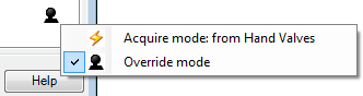
Furthermore, If you select one of these three valves and click on the “Override Mode” icon and change it to “Acquire mode: from Hand Valves” there is not a Knife, Pinch or Rotary Valve to even set these items in the acquired list. There lies our problem that we need to fix.
DO NOT HIT APPLY OR OK but SELECT CANCEL to get out of the Project Setup. There is no need to close the software. Using Windows Explorer, navigate to the root directory of your project, locate and right click on the file PIDToSpecClassMapping.xml. Select Open with > Notepad. Search the file using CTRL-F for Valve_SubTypes. Just below this is a list named ExternalPropertyName where we need to add each valve. I just copied Gate::::Inline at the beginning of the list and pasted it to the end of the list three times changing it to Knife, Pinch and Rotary as seen below in the highlighted text. Each one is separated by a “,” then the valve type followed by four colons (:) and ending with the word “Inline”. If you like, you can copy the highlighted text below and paste it straight into your XML file.
If you need other versions of a particular valve such as a 3 Way valve, then add another one that says “3-Way” instead of “Inline”. You can look over the list and pretty much figure out the formatting for different types of valves.
When you are done, save the file and return to Plant 3D or P&ID.
<PnPClassMap> <Name>Valve_SubTypes</Name> <ExternalObjectName>Valve</ExternalObjectName> <PropertyPairCollection> <PnPPropertyPair> <Name>PnP_PID_To_3d_Valve_Class_Subtypes</Name>
<ExternalPropertyName>Gate::::Inline,Ball::::Angle,Butterfly::::Angle,Check::::Angle,Diaphragm::::Angle,Gate::::Angle,Globe::::Angle,Needle::::Angle,Plug::::Angle,InclinedSeat::::Angle,Tank::::Angle,Float::::Angle,Cock::::Angle,Corner::::Angle,MultiPort::::Angle,Butterfly::::Inline,Butterfly::::3-Way,Check::::Inline,Diaphragm::::Inline,Diaphragm::::3-Way,Check::::3-Way,Needle::::Inline,Needle::::3-Way, Plug::::3-Way,Ball::::3-Way,Globe::::3-Way,Gate::::3-Way,InclinedSeat::::3-Way,Tank::::3-Way,Float::::3-Way,Cock::::3-Way,Ball::::Inline,Float::::Inline,Globe::::Inline,Ball::::4-Way,Butterfly::::4-Way,Check::::4-Way,Corner::::4-Way,Diaphragm::::4-Way,Gate::::4-Way,Globe::::4-Way,Needle::::4-Way,Plug::::4-Way,InclinedSeat::::4-Way,Tank::::4-Way,Float::::4-Way,Cock::::4-Way,MultiPort::::4-Way,Plug::::Inline,Knife::::Inline, Pinch::::Inline,Rotary::::Inline</ExternalPropertyName><ValueMaps />
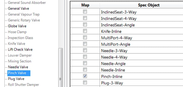
Return to the Project Setup and select P&ID DWG Settings > Pipe Specs in P&ID > Pipe Spec Object Mapping. Next select the icon for the valves. Select the Pinch Valve and click on the “Override Mode” icon and change it to “Acquire mode: from Hand Valves”. The list is in alphabetical order so locate Pinch-Inline and activate it.
Rinse and Repeat for the Knife and Rotary Valve. Click OK to return to your project.
Using the P&ID Painter for Off Spec Piping, in the example below (which is from the previous article where I am using the out-of-the-box CS150 Spec), all of the 1/8” piping and components are red because there are not any 1/8” piping or valves in the spec. The 16” line is blue because that one is in the spec and while the 30” pipe is out of spec the 30” valves are in the spec. The pinch valves are cyan on all three lines because this image is from before they were mapped and cyan is the color of the Mechanical layer.
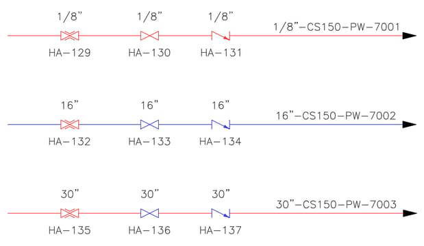
Now that I have mapped the pinch valves the results in the new image below show the pinch valves in red. This is because there are still no pinch valves in the out-of-the-box CS150 Spec, but at least now the results of the P&ID Painter are correct. In addition, the hatching on the tool palette is now working correctly for these valves as well as with part substitution and the Data Manager.
Plant 3D Class Mapping For P&ID Object Mapping
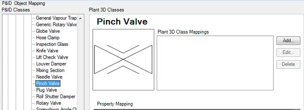
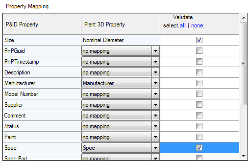
Turning our attention to the Plant 3D side of the software, in the Project Setup under Plant 3D DWG Settings > P&ID Object Mapping on the right hand side of the pane under P&ID Classes locate Engineering Items > Inline Assets > Hand Valves, select Pinch Valve. Under Property Mapping, not one P&ID Property has been mapped to a Plant 3D Property nor can it be mapped until we add a Plant 3D Class Mapping.
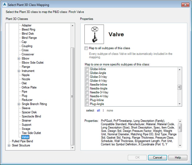
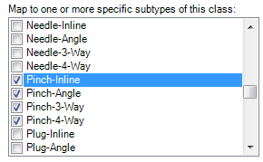
Select Add and in the Select Plant 3D Class Mapping dialog box navigate to Piping and Equipment > Pipe Run Component and select Valve. In the list of subtypes for this class you will see that once again there is not a Knife, Pinch or Rotary Valve in the list. Without a way to map these valves, Validation will never occur on these valve types.
Once again, cancel all the way out of Project Setup. This time you will also need to exit completely out of the software. Using Windows Explorer open in Notepad, choose the file named P3dEnumeration.xml which in a default install is located in C:\Program Files\Autodesk\AutoCAD 2017\PLNT3D\en-US or C:\Program Files\Autodesk\AutoCAD 2018\PLNT3D\en-US depending on your version.
You should see the EnumValueList right near the top of this file which contains several lines that start with P3dEnumValue. Copy any one of those lines (for my example I am copying the top one for “Ball” valves). I paste a new line and change Ball in both places within the line to Pinch, Knife and/or Rotary. Sequence matters in this file so if you want them to be alphabetical then you must place them in the correct spot in this list. If you put all three after “MultiPort” then they will appear after MultiPort in the software.
<P3dPropEnum name="ValveBodyType">
<EnumValueList>
<P3dEnumValue GlobalName="Ball" LocalName="Ball"/><P3dEnumValue GlobalName="Butterfly" LocalName="Butterfly"/><P3dEnumValue GlobalName="Check" LocalName="Check"/><P3dEnumValue GlobalName="Corner" LocalName="Corner"/><P3dEnumValue GlobalName="Diaphragm" LocalName="Diaphragm"/><P3dEnumValue GlobalName="Gate" LocalName="Gate"/><P3dEnumValue GlobalName="Globe" LocalName="Globe"/><P3dEnumValue GlobalName="Knife" LocalName="Knife"/><P3dEnumValue GlobalName="Needle" LocalName="Needle"/><P3dEnumValue GlobalName="Pinch" LocalName="Pinch"/><P3dEnumValue GlobalName="Plug" LocalName="Plug"/><P3dEnumValue GlobalName="InclinedSeat" LocalName="Inclined Seat"/><P3dEnumValue GlobalName="Rotary" LocalName="Rotary"/><P3dEnumValue GlobalName="Tank" LocalName="Tank"/><P3dEnumValue GlobalName="Float" LocalName="Float"/><P3dEnumValue GlobalName="Cock" LocalName="Cock"/><P3dEnumValue GlobalName="MultiPort" LocalName="Multi Port"/>
</EnumValueList></P3dPropEnum>
Save and exit the file.
Before we see the results let me add a couple of comments about this file. It must reside in the folder you found it in on your local machine. You can’t move it to the network and place it in a network support path for all to see. If you work in a company with multiple Plant 3D users, this file will need to be updated on each user’s machine. You can copy the file though and overwrite it on each user’s machine so that they match, but make sure the user does not have Plant 3D open when you do that.
In addition, when you upgrade from one version to a new version like from 2017.1 to 2018, there is no guarantee that the new version of this file is identical to the old version and you want to make sure you keep any changes that may have been made in the new version. Therefore, do not overwrite the new file with the old file. You will need to make these changes to the new version of the P3dEnumeration.xml file. I know it’s a bit of a hassle, but it is better to be safe than sorry.
Now for the grand finale – drum roll please – open Plant 3D and in the Project Setup under Plant 3D DWG Settings > P&ID Object Mapping on the right hand side of the pane under P&ID Classes locate Engineering Items > Inline Assets > Hand Valves and select Pinch Valve. Select Add and in the Select Plant 3D Class Mapping dialog box then navigate to Piping and Equipment > Pipe Run Component and select Valve. What’s that you see in the list of subtypes? Activate the Pinch Valves you want to map, select OK and then map the properties between P&ID and Plant 3D, as well as which ones you want to use when Validating. For consistency, I would suggest looking at other valves that are already mapped and map the new valves the same as the existing ones.
Rinse and Repeat for the Knife and Rotary Valves then hit OK to save and exit the Project Setup and your mission is complete.

Comments