 Most people who have done any customization in Plant 3D are familiar with creating Class Properties in the project, but what if you want to pass preset information from the Spec into those Class Properties? Though it may feel like it’s a bit time consuming to populate in the Spec, it is not that difficult to do, and in reality, it does not take that long either. Plus, once it is set up, it can be passed from project to project when you use the "Copy Project" function. You can use that information in custom tags, annotations, BOM's, Iso's, Reports, or anywhere in the software that you use any out-of-box properties.
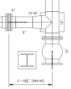
Recently I had a client who was using Alternate Units in his dimensioning to show the Imperial dimension with the metric conversion in brackets like the 2'-10 1/4" dimension in the image to the right. However, when they use the Ortho Annotation to add something like the Nominal Diameter to pipe, flange, reducer, tee, and valve, the only option is to show the Imperial Size. There is not an out-of-box method to show the Metric Size in brackets, just like the dimension.
Their first thought was to define a calculating property that converts the size to metric. The problem with this method is while you can multiply 8 x 25.4, the result would be 203.2, which would not be a valid metric pipe size. Plus, there is not a method in the calculating property to round, and even if there were rounding a straight conversion like that would not always give you the correct actual metric pipe size. The solution? Define a property in the Spec that you can input the correct metric size for each Imperial size of pipe, flange, valves, fittings, and even bolts. Then pass that information right into the components within your drawings, annotations, reports, etc. Sounds simple, but there are a couple of tricks that you need to know to pull this off, and we are going to use this example to walk you through step by step with Custom Spec Property Definitions and Custom Project Property Definitions.
Custom Spec Property Definitions
The majority of our work takes place in the Spec Editor mainly because that is where we will initially input all the data. My personal opinion is that you close Plant 3D when you modify a project spec, but that is your call. I have found that things just seem to work better that way. Open the Spec Editor and then open the specific Spec you would like to modify. I am using the CS150 spec, which is, for the most part, out-of-the-box. The exception is that I have added additional sizes beyond 24", slip-on flanges, removed some valves I didn't need and added some custom Instruments. I only mention this so that when you see some of these in the images, you don't email me to complain those items are not in your spec. However, everything we are doing can be performed on the out-of-the-box CS150 spec as well as any other spec you might want to try this on.
We will start with the piping, so locate the pipe section in the spec and double click on the Pipe itself.
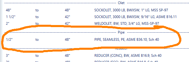
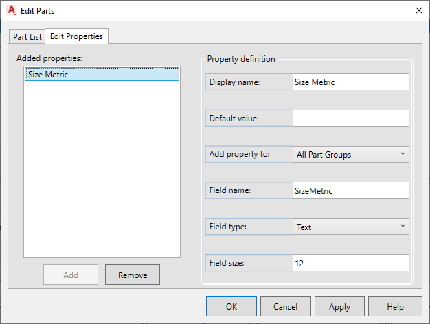
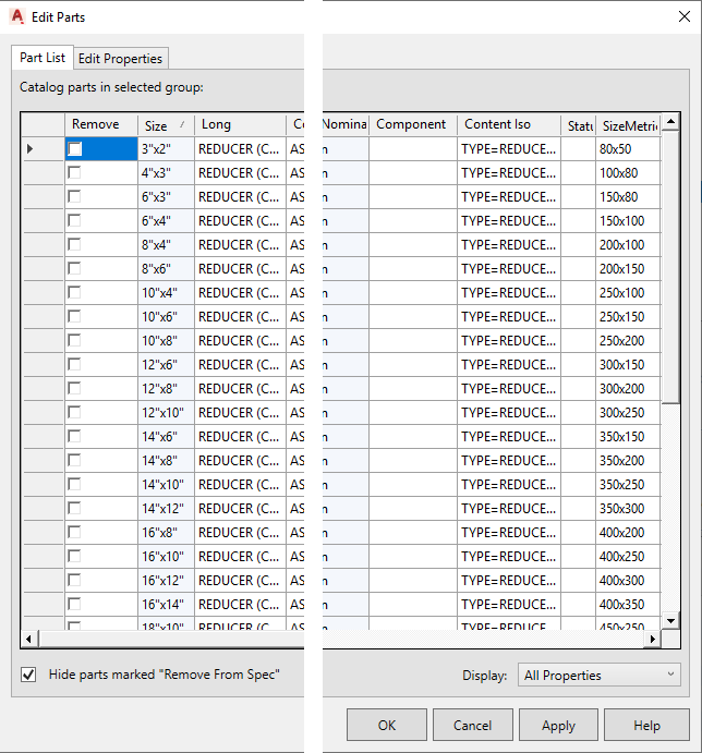
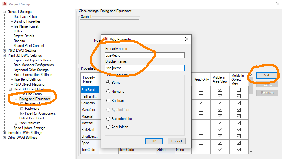
This will open up the Edit Parts Dialog Box. Select the “Edit Properties” tab. This is where we create the Custom Property Definition within the Spec, and we are going to create one named SizeMetric filled out exactly like the image below. However, a little explanation is not a bad thing.
- The display name can be whatever you want to see as the column header when inputting the data. It can contain spaces and special characters.
- The default value is exactly what it means. Whatever is entered here is what every item in your Spec will initially be set too. For that reason, I am leaving it blank in this instance.
- For Add property to there are two choices.
- “Current Part Group Selection” means the property will be added to Pipe and Pipe alone because we are in the Edit Parts for Pipe.
- “All Part Groups” means everything in the Spec will have this property. Pipe, Valves, everything. We could create this property in a Reducer, and Pipe would have inherited it.
- The Field name can contain only letters, numbers, and underscores.
Now you say, "But it will let me use spaces and special characters." True, it will allow for that in the Spec, but for this to work, we will need to create a Class Property in the project that matches the Field name EXACTLY, and Class Properties can contain only letters, numbers, and underscores. Therefore, the Field name can only contain letters, numbers, and underscores. It is also important that you keep track of the Field name for later since it must match EXACTLY. - Field type can be Text, Numeric Value, or True/False (checkbox). In our case, we are going to make it Text because Reducers have two sizes with an "x" in it, which means it will need to be a String.
- If Field type is not Text, then you can leave Field size However, if it is Text, you must define the Field size. I chose 12 because my largest Reducer (48x42) would be nine characters (1050x1200), so I might as well add a little slush for the future just in case.
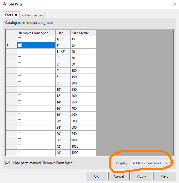
When completed, select Add to create the new Property, and you will see it in the "Added properties" window. Then select Apply to make it available for editing, which we will now do by selecting the “Part List” tab.
On the “Part List” tab, change the Display to "Added Properties Only." Now you can see the Size of the Pipe and the Property Definition that we just added. Size Metric is empty for each size because we did not set a default value. Now we just need to enter the metric equivalent for each pipe size as shown in the image below and select OK when finished.
Now comes the part that will feel so very time consuming, but in reality, it does not take very long at all. It's just monotonous. I did my entire spec in less than an hour, and that included a couple of sanity breaks. The property has been created for every part since we used "All Part Groups", but the data has only been added to Pipe, assuming you only have one pipe definition in your spec as I have. You will need to add the values to every item in the Spec. In my case, I added the metric sizes to every Flange, Blind Flange, Elbow, Tee, Valve, Olet, Cap, Gasket, Strainer, and Instrument.
For Reducers, Reducing Tees and similar components like Relief Valves, I entered the sizes in a format similar to the imperial Size. In other words, a 10"x8" was entered as 250x200. By the way, you can leave the Display set to “All Properties” and locate SizeMetric for editing if you choose; it just might be a little more difficult to see the sizes in some instances. The image below where I entered the data for Reducers is displayed this way.
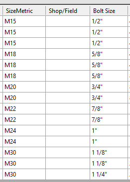
Bolts are the one item I did completely different. I still used the SizeMetric property, but I wanted the size of the bolt, not the size of the pipe. Also, bolt lengths are calculated when placed in your model based on flange thickness. Because of this, I only included the Bolt Size in the Spec and will need to enter the lengths after the fact via the Data Manager.
At this point, my Spec is complete, so I just need to Save and Exit the Spec Editor.
On a side note, let's say this is not something I am going to use in every project, but I use this same spec in every project. It does not hurt a thing having this property and data in my spec if I do not need it in the project. I am in complete control of when I need to show the data and when I don't, but once it is entered, I should not have to enter it again, and the data will be there ready to go when I do need it.
One last comment regarding the specs: If I add new items to the spec from the catalog or additional sizes, I will need to add the Size Metric data to those items. That's just the nature of the beast and no different than anything else I add to a spec.
Custom Project Property Definitions
Now I want to utilize all that data in my project, but when I open my Plant 3D Project and route some pipe, it's not there. That's because, for the data to pass from the spec into the component, the project needs to have a matching class property.
So open up the Project Setup and go to Plant 3D DWG Settings > Plant 3D Class Definitions > Piping and Equipment. We need to add our class property at this point to have it available to both Pipe Run Components and Fasteners. Select Add and in the Add Property Dialog Box set the Property name to SizeMetric and the Display name to Size Metric. Remember: The Property name in the project must match the Field name in the Spec for the info to be passed. When completed, select OK to add the property and OK to exit the Project Setup.
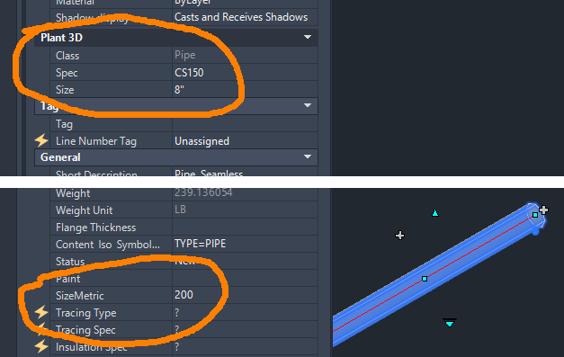
Back in the drawing, Route a new 8" Pipe. Select the pipe and look at it in the Properties Palette or look at it in the Data Manager, and you will find SizeMetric will be defined as 200.
But there is one little problem. This worked as expected on a new component, but what about existing components? If you look at any existing Pipe Run Component SizeMetric is empty. If you are like me, you really do not want to have to redraw your entire project. That brings us to one of Rick’s Tricks.
Rick’s Tricks: Updating The Existing Pipe Run Components
All we need to do is change each component to another spec and then back again. However, we can't change it to another pressure class, or it will disconnect everything. We also can't change it to a spec that has different sizes or components because that will not only disconnect objects but change them into place holder objects. What we need is an identical temporary spec to change to so that everything is maintained, and then we can change it back to the original spec.
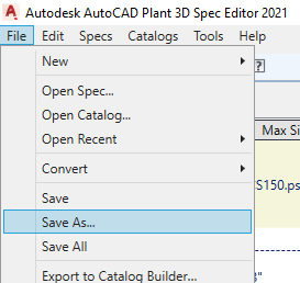
To do this, Open the Spec Editor and then open the Spec, which in my case, is CS150. Go to File > Save As and save the spec in a new location outside of the project with a new name. I named mine CS150tmp. After that is done, exit the Spec Editor.
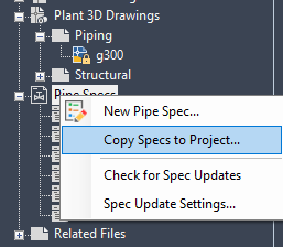
Back in the Plant 3D Project Manager, right-click on Pipe Specs and select Copy Specs to Project. Browse to the location of the temporary spec and select the pspx file (CS150tmp.pspx) and then select Open. The temporary spec should now appear in the Project Manager.
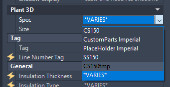
Now we need to select all the Pipe Run Components that are using our new Spec with the new property in it. I have found that it is best to Hide all the Equipment, Steel, and any other objects that are not assigned to our new spec. The last thing you want to do is to have SS150 components and CS300 components to be changed to CS150 components. It is essential that you maintain the correct Specs to components. Once I have all the correct Pipe Run Components selected, in the Properties Palette, change the Spec to the temporary Spec. When it has completed, which can take a minute or two, DO NOT HIT ESC or DESELCT ANYTHING – just immediately change it right back to the real spec.
Since the temporary spec was an exact copy of the real spec, no components should get disconnected, nor should you receive any error messages. If you do, then most likely items that belonged to a different spec were included in your selection set. The best thing to do would be to exit the drawing without saving it then reopen the drawing again, being careful to only select items in the correct spec. Otherwise, you will need to find and fix the individual items. Either way, Validate your Project and confirm everything is working as it should. If you did not receive any error messages, everything should validate the same as it did before you made the change. If you had errors, then validation will help you find anything that was disconnected, and anything changed to a place holder part.
After you are satisfied everything is correct, and you have confirmed that the existing Pipe Run Components now have the correct property info for Size Metric, you can remove the temporary spec from your project.
Using The Custom Property Information
The new property is now ready to be used anywhere you can use an out-of-the-box property. We will walk through one example for those who might be new to this by making a new ortho annotation similar to the out-of-the-box Nominal Diameter ortho annotation.
Return to the Project Setup and go to Plant 3D DWG Settings > Plant 3D Class Definitions > Piping and Equipment. In the bottom right corner, change the Ortho Annotation Setup to “Nominal Size [Size]” then select Add Annotation. In the Symbol Settings Dialog Box, set the Symbol Name to @SizeMetric, then click OK. I like to name my custom annotations using the "@" symbol so that they all sort together at the top of the list.
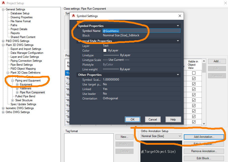
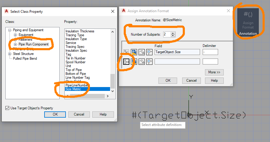
Next, select Edit Block, and it will open up the new annotation in the block editor. Select Assign Format and then select the attribute, which in this case, says #(TargetObject.Size). Now in the Assign Annotation Format dialog box, set the Number of Subparts to 2. On the new subpart, select the button that looks like a pump. In the Select Class Property Dialog Box for the Class select Piping and Equipment > Pipe Run Component and for the Property select Size Metric. Then select OK.
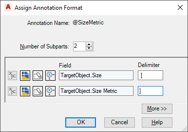
Back in the Assign Annotation Format Dialog Box set the first Delimiter to “ [“ and the second Delimiter to “]". There is no need for quotes on the delimiter since they were an attempt at showing that I had whitespace before that first bracket. Now select OK then Close Block Editor and Save the Changes. One more OK to exit the Project Setup.
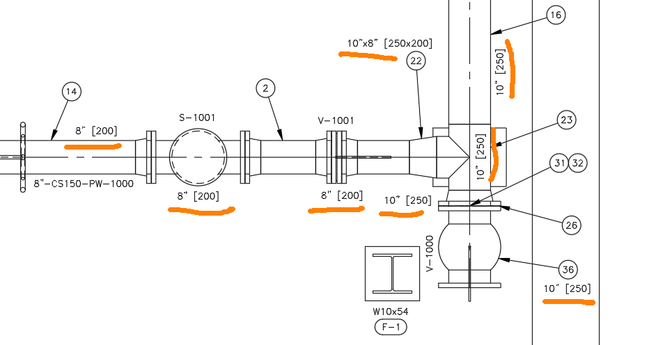
We now have a working ortho annotation. In the image below, you can see where I used this new annotation on Pipe, a Strainer, Valves, a Flange, a Reducer, and a Tee.
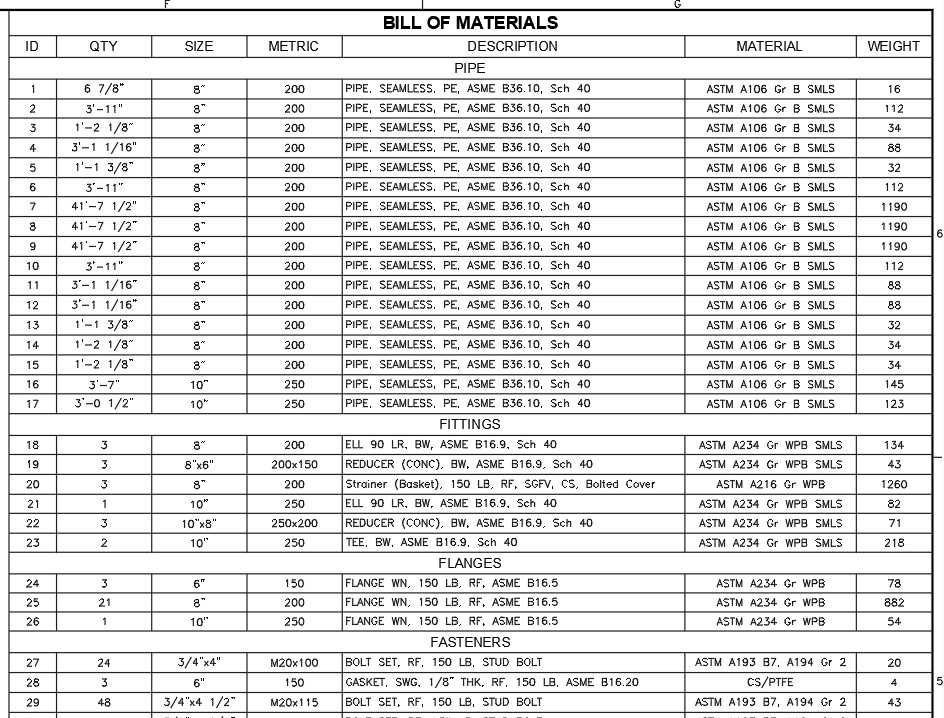
In the final image below, you can see where I set up a column in a BOM to pull this same data. Notice the Bolts have the lengths added to them. I used the Data Manager to sort bolts by length so that I could add the correct metric length to each bolt using Copy and Paste, making that a relatively quick and easy process.
This new property is now available to use in tags, annotations, BOM’s, reports, and Iso’s. Just remember - you will only get out of the software what you put into the software.


Comments