When project data includes Navisworks® NWD and NDC files, you can now link these models into your Revit projects for coordination purposes. This exciting new functionality also allows for any file formats that are supported by Navisworks to be included within the coordination model link.
Coordination models can be inserted using origin to origin or shared coordinate positioning. Coordination models support Absolute and Relative path types.
Coordination models render using native Navisworks engine which currently supports a consistent shading display. They appear in all views including sections or elevations, floor plans and 3D views.
Link a Coordination Model
Link a file from Navisworks and use it as a reference for a Revit model, providing context for the design:
- Obtain a file containing the model created using other CAD software (or request a NWD file of the model be provided). For a list of supported CAD file formats, see the Navisworks help.
- In Navisworks, do the following: (If an NWD file is provided skip this step)
a. Open the CAD file.
b. Save the model to an NWD file. - In Revit, link to the NWD file or its corresponding NWC cache file, as follows:
a. Click Insert tab > Link panel > (Coordination Model).
b. In the Coordination Model dialog, click Add.
c. Navigate to the target NWD or NWC file, select it, and click Open.
d. Click OK.
e. The linked model displays in the currently active view.
1. (Optional) Select the linked model, move it to the desired location, and pin it in place so it is not inadvertently moved out of place.
f. Open and navigate other views to see the coordination model from different viewpoints.
Using the coordination model in Revit
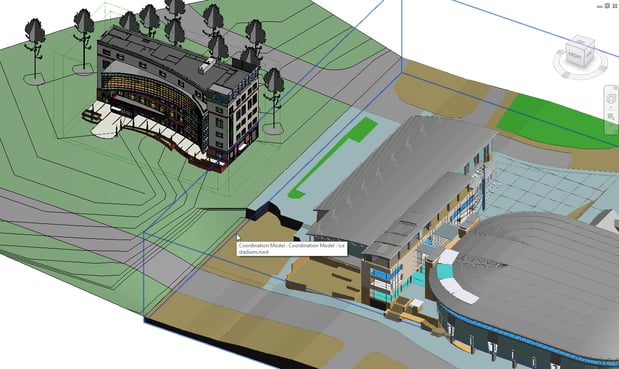
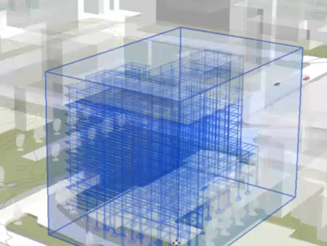
When you link a coordination model into a Revit model, the coordination model displays in the current view. It is surrounded by a bounding box, which displays when you move the cursor over the coordination model. When you select the box, the status bar displays the family and type Coordination Model: Navisworks Model, followed by the Navisworks model name. The Properties palette displays the file path, name, and other properties for the coordination model.
- To select the coordination model more easily, use the Select elements by face option.
- Display the coordination model in 3D views and 2D views, including plans, elevations, and sections.
- Pin the coordination model to lock it in place, so it does not inadvertently move in relation to the Revit model.
- Define phasing for the coordination model.
- Define transparency for the coordination model to distinguish it from the Revit model. Use the Visibility/Graphics dialog to set its visibility and define transparency. Defining Transparency Help
- For worksharing, add the coordination model to a workset.
- Print the coordination model as part of a Revit view.
- Export the coordination model to an image as part of a Revit view.
- Unload the coordination model to temporarily remove it from the model (for example, to improve performance). When you reload the model, it reloads to the same position and orientation. Managing the Coordination Model
- Reload the coordination model to reflect recent updates.
- Remove (delete) the coordination model from the Revit model.
- Because textures are not included with the coordination model, it cannot be rendered as part of a Revit view.
For More information:


Comments