Have you ever had to design an assembly where there was a common dimension(s) in all of your parts? Maybe a diameter, hole to hole spacing or clearance around a part is used in more than one part. If it’s early in the design phase, you may not know what this dimension will be, so you have to start with an educated guess. If your educated guess was incorrect, you will have to open each file and edit each part with this new updated dimension. In this blog article, I will show you a quicker, more efficient way to do this by exporting and importing parameters.
Basic Steps
The basic steps to link and share your parameters/dimensions across your cad models are as follows:
- Define which parameters will be shared
- Export the parameters (Optional)
- Import the parameters
- Use the parameters
Steps in Detail
For my example, I am going to use the following three parts.
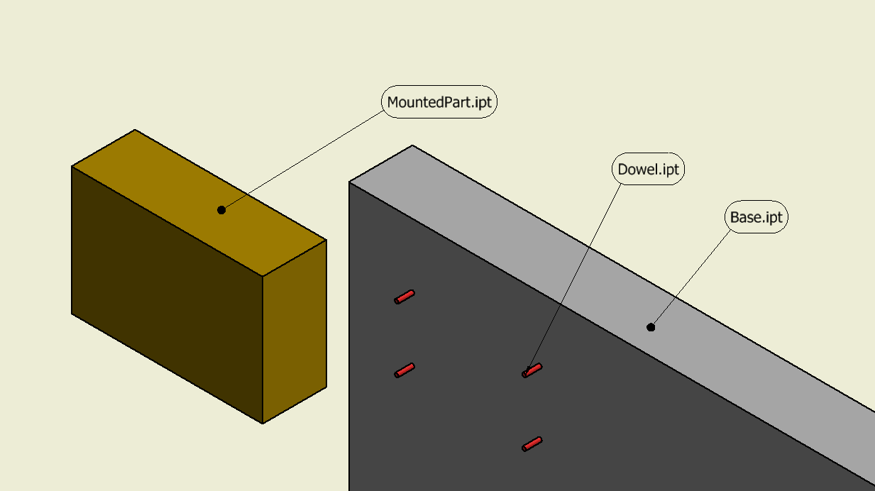
If it isn’t obvious, MountedPart.ipt will mount on Base.ipt located by the Dowel.ipt. The dimensions I want to share are in Base.ipt…they are the dowel pin diameter and the spacing between the dowel pins. The dimensions are named “dowel”, “Height” and “Wide”.
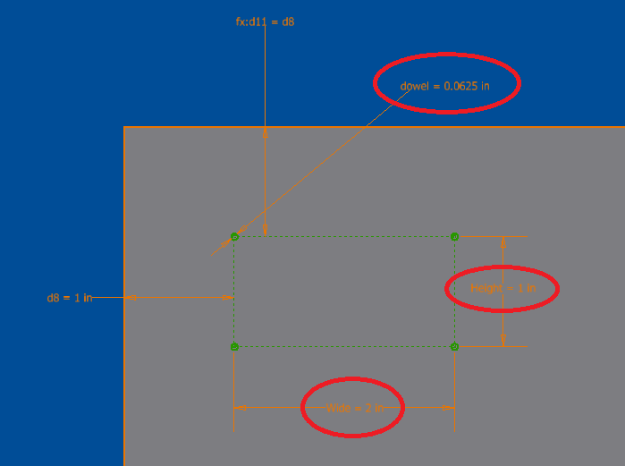
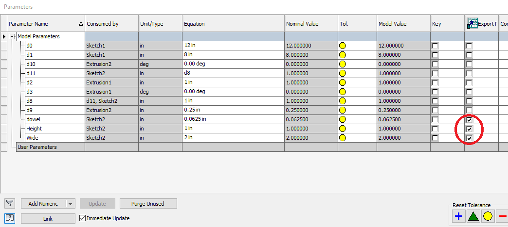
Once the dimensions are defined, open fx Parameters and click on export.
Next, I will create a new part called MountedPart.ipt. The first thing is to import the parameters from Base.ipt.
Open fx Parameters and click on Link – select Base.ipt. **(You may have to change the “Files of Type to *.ipt, *.iam)**
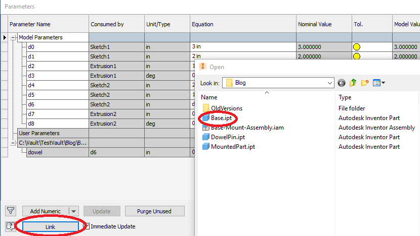
Once Base.ipt is selected, you will get the dialog box below, and you can choose which parameters to import. If you select a parameter that wasn’t exported, it’s not a problem. You will be presented with “Selecting a non-exported object will modify the base component to mark the object <xx> for export”….just click ok.
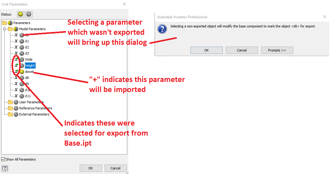
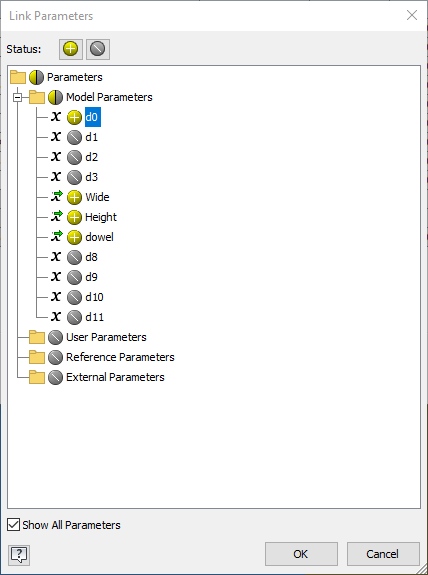
The parameters I have selected to import are d0, Wide, Height, and dowel.
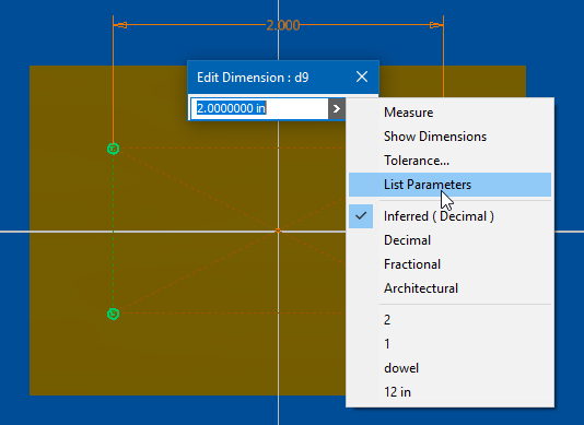
Next, I will use the parameters that were imported in my sketch. Create a sketch, select Dimension – select the object to dimension – click on the “arrow” – select List Parameters – finally, select one of the imported dimensions.
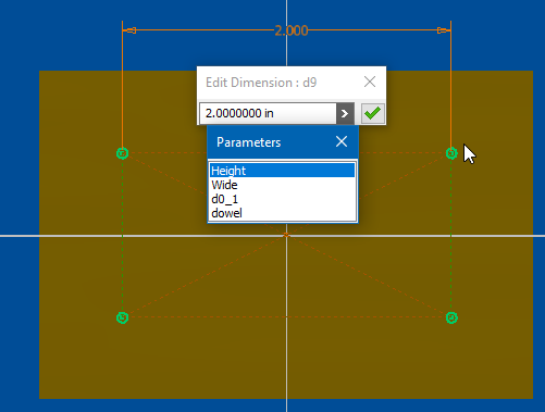
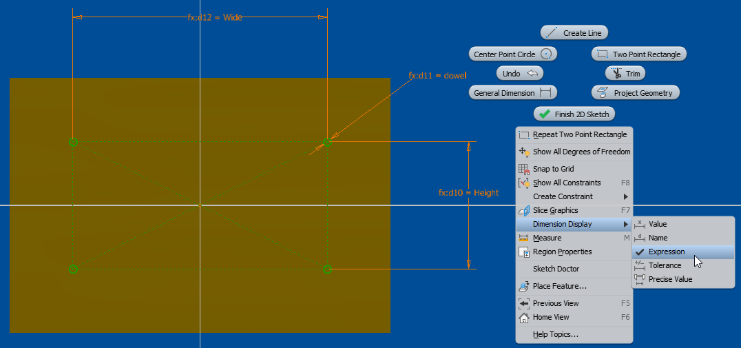
Rinse and repeat for the width/wide and the dowel diameter. (I didn’t outline the steps, but I did the same for another new part called Dowel.ipt. I imported “dowel” and dimensioned it to the dowel diameter). Here is what the finished sketch looks like for MountedPart.ipt : (I also changed my Dimension Display to Expression. Right-click in the sketch and select Dimension Display – Expression)
I won’t go into the boring details on how to assemble and constrain, but here is the final assembly:
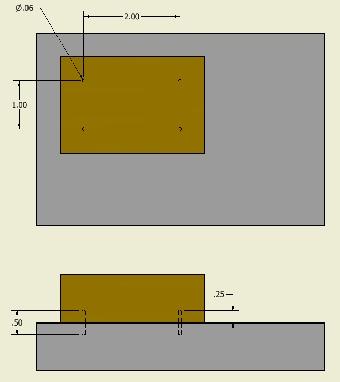
The advantage of this workflow is manipulating all the parts and the assembly from one part (Base.ipt). If you had to change the dowel pin diameter or the spacing between them, open Base.ipt , edit the dimension(s), and click Update in the assembly environment. No need to open and edit MountedPart.ipt or Dowel.ipt.

But wait, there’s more!
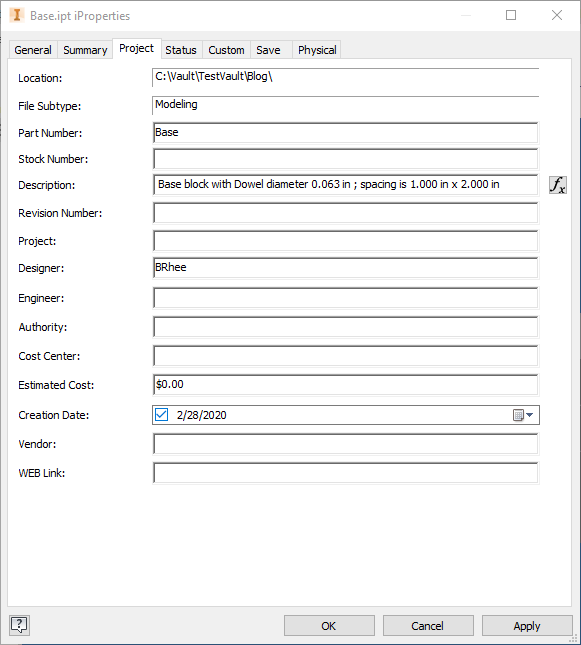
After selecting export, you will notice on the iProperties – Custom (tab) – the parameters that were selected to be exported. These can be used to create an expression in an iProperty field!
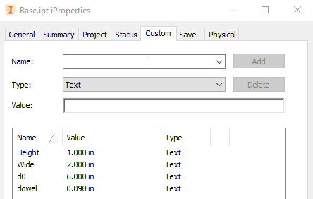
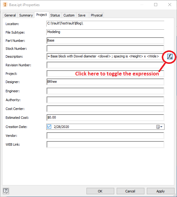
To create an expression, start with “ = “ and surround your custom parameter with “ < “ and “ > “. Remember, it is CASE SENSITIVE!
Wrapping up….
Exporting and importing of shared dimensions will lead to more intelligent designs and quicker edits. Imagine if you had many parts that had common dimensions but weren’t linked? Now you need to change a common dimension on all of the parts. Not only would it take longer to open and edit each .ipt file, but what if you forgot to edit one part? It could be disastrous! If you take the time early in the design process to link all pertinent dimensions across all your parts, changes to the design will become much easier. You won’t have to open and edit all the parts and worry about forgetting one! So take advantage of this workflow and good luck!


Comments