This article was originally released in the fall of 2013; however, I have received several emails since then about an issue users were having when validating their projects after implementing the changes in the article. The validation error would be under the heading “Unmatched model inline fittings” and would show every piece of pipe in the 3D model.
For each pipe it stated something similar to “This Pipe with tag 8”-CS150-NA-1001 (size 8” and spec CS150) was not found on any pipe line NA-1001 in any of the P&ID drawings in this project.” My only answer was to ignore the issue until now. After throwing every dart I could think of I have finally figured out what was causing the error. It was the Pipe Line Number Tag Format setup in the Pipe Run Component. Out of the box, there is not a tag format for the Pipe Run Components and evidently the validation will not find pipe in the P&ID if you add a format.
I used the format to simplify the tags in both the Ortho’s and the Isometric’s and had a one stop setup on the plant side in case users ever needed to change the tag format for a project in the future. Fortunately, I was able to come up with a different method that still accomplished this without sacrificing the validation process, which is why I am updating this article today. For those who have already implemented the original article I have marked the sections that require a change as REVISED.
Because Plant 3D does not have a method for implementing a change like this to every project these revisions will need to be made in each existing project that you have implemented the original article on. For that reason you may choose to continue with the validation errors on existing projects but in case you would like to make these changes to existing projects I have added a new section at the end of this article entitled “Implementing These Revisions On Existing Projects”. If you choose not to update the existing projects I would suggest you update any template projects in order to validate in future projects.
Lastly, if you have already implemented the original article you may skip straight to the first revision which is entitled “Create A Pipe Line Number Property”. If this is your first time with this article then proceed forward from this point.
Cross-functionality between AutoCAD Plant 3D and AutoCAD P&ID adds intelligence and continuity to the design process, enabling the drawings to interact with one another from P&ID through Piping Isometrics. Straight out of the box, however, there is great inconsistency with the pipe line numbers.
The images below shows that when tagged, your line numbers are not the same in the P&ID, Model, Ortho and Isometric drawings:
P&ID Line Number
Pipe Routing Line Numbers 
Pipe Tool Tip 
Ortho Line Number 
Isometric Line Number
Today we will show you how to setup your project to have the Pipe Line Numbers appear exactly the same from P&ID to Iso. The one exception will be the Pipe Routing Line Numbers, which most would agree do not need to match every pipe size and spec, however it would be helpful to include the Service of the pipe run when routing pipe.
PLEASE NOTE: While you can apply these properties to an existing project, it will take additional work on your part to transfer existing drawings into this system. Therefore results will vary on an existing project until all entities have been manually updated. In order to get the best and easiest results from these settings it is recommended that this be done before you create the first drawing within a project. These settings will also transfer into a newly created project based on a project that these procedures have been added to.
After you have created a new project in Plant 3D you are ready to proceed. We are going to make the out of the box line number system our standard throughout this project, however you can make this conform to any system you might require. P&ID uses this system: Size-Spec-Service-Number.
Using whatever method you prefer, open the “Project Setup”.
First we will setup the P&ID side in order for it to shake hands with the Plant side. In the Project Setup dialog box tree on the left, expand and select the following: P&ID DWG Settings > P&ID Class Definitions > Pipe Line Group

In the Main Window of the dialog box under Tag Format select Line Number then click on the Modify button.

In the Tag Format Setup set the Number of Subparts to “2”. Click the “Select Class Properties” button for each subpart and change the first one to TargetObject.Service and the second one to TargetObject.Line Number.

Click OK but do not exit the Project Setup. I recommend you click “Apply” in order to save your work and not lose anything by accident.
We are ready to set Plant 3D up to match. In the Project Setup dialog box tree on the left, expand and select the following: Plant 3D DWG Settings > Plant 3D Class Definitions > P3D Line Group

Just as before, In the Main Window of the dialog box under Tag Format select Line Number then click on the Modify button.
In the Tag Format Setup, set the Number of Subparts to “2”. Click the “Select Class Properties” button for each subpart and change the first one to TargetObject.Service and the second one to TargetObject.Number.
This accomplishes a couple of things. It will allow the Service to be included in the Pipe Routing Line Numbers drop down as well as the layer names, making the line numbers easier to maintain. It will also allow you to set the Service correctly while routing your pipe which will keep the Pipe Line Numbers that we use in P&ID, Orthos and Isometrics consistent. Click OK and in the Project Setup click Apply.
REVISED: CREATE A PIPE LINE NUMBER PROPERTY
In the original article it was at this point that we created the Pipe Run Component Tag Format. Since that was the culprit for the validation error we need to use a different method. If you have implemented the original article already then you will need to fix this issue by following the instructions at the end of the article entitled “Implementing These Revisions On Existing Projects” but you can wait until after you have completed all of the revised steps.
Also in the original article right after Ortho’s in order to setup the Isometrics we created a new Plant Property. That step has now been moved to this section because we can use this same property for Ortho’s as well as Isometrics. It’s a little more in depth now since we can’t use the Tag anymore but you can modify the previous version to this new one.
We need to setup a Property to match the “Size-Spec-Service-Number” system of the P&ID’s by creating a Custom Design Calculation Property and then use that in my Ortho and Isometrics by way of a little known command named “PlantDesignCalcProperties”. When you add a property using this method it will only be added to your active project, however I recommend you use this sparingly. Always create your properties in the Project Setup unless you know EXACTLY what you are doing and have a unique situation like this one where we need to concatenate several properties together.
That being said, at an AutoCAD Command Prompt enter the command PlantDesignCalcProperties and press ENTER.
![]()
Welcome to the Calculated Properties Manager. Make sure you follow this part step by step – Click the “Piping” tab and under Engineering Items select “PipeRunComponent”. If you have already done this you may select PipeLineNumber from the drop down box. Otherwise, create a Property name with NO SPACES called PipeLineNumber and in the drop down box set it to “String”.
If you have done this already, blank out the text in the open box area below Property name.
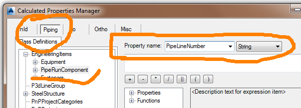
Under Properties, locate and double click on “Size” to add the property in the open box area below Property name. You then need to add double quotes to the word “Size” or else none of this will work. None of the remaining properties require the double quotes.
Next click the button that has the double pipeline (||). This is used to concatenate the properties together. You will then need to add the dash by typing ‘-‘ and it must be in single quotes followed by another double pipeline (||). Next double click the property “Spec”, add another double pipeline and then another dash in single quotes (‘-‘) followed by a final double pipeline (||). Lastly locate “LineNumberTag” near the bottom of the Properties and double click to add that one. In the end it should look exactly like this: "Size" || '-' || Spec || '-' || LineNumberTag
If you prefer you can type this line in, but make sure there are no spaces in LineNumberTag and remember that this is case sensitive. If anything is incorrect in this format it will not work.
After this is complete, Apply and Close.
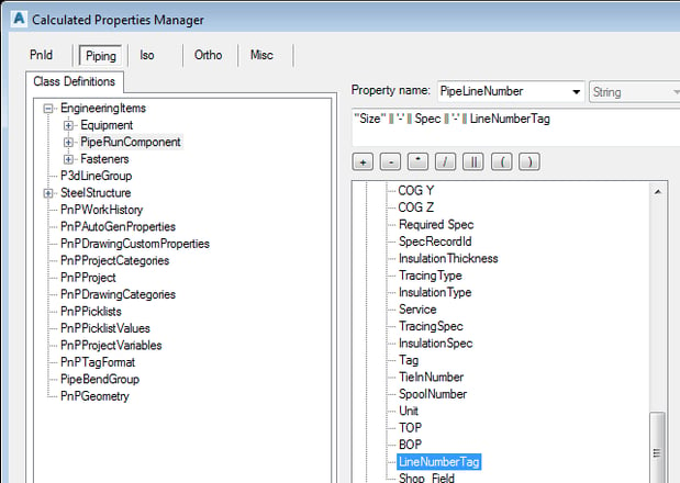
As a side note, if you ever have a project that requires a different Pipe Line Number format on the Orthos and Isometrics and the project was based on everything in this article, you can change the format of this property and everything we have done in the remainder of this article will automatically update.
REVISED: CREATE AN ORTHO TAG
At this point we are ready to create our Ortho Annotation Tag. In the Project Setup dialog box tree on the left, expand and select the following:
Plant 3D DWG Settings > Plant 3D Class Definitions > Piping and Equipment > Pipe Run Component
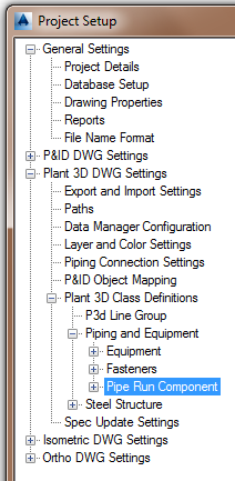
In the Main window under “Ortho Annotation Setup” in the drop down box either select your existing @Pipe Line Number and go straight to Edit Block skipping the next few lines but for the first timers change it to Full Line Number Callout [Size-Line Number Tag-Spec] as a starting point. Then select Add Annotation. In the Symbol Settings dialog box set the Symbol Name to @Pipe Line Number then Click OK.
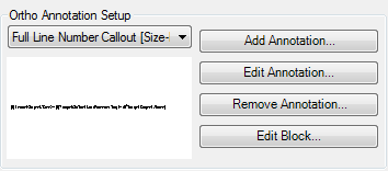
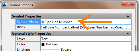
While the “@” symbol is not necessary it will cause this new Annotation to sort to the top of the list. Therefore when you are placing Annotations in an Ortho, “@Pipe Line Number” will be the default option which is just one more nice little time saver.
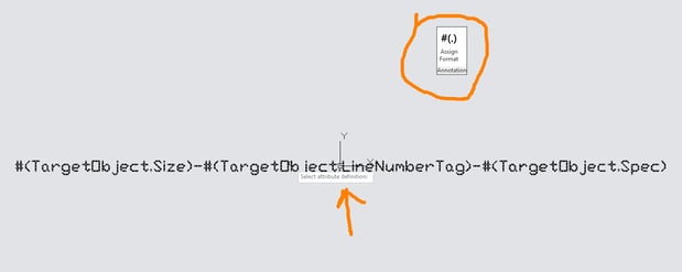
Now select the “Edit Block” button to open up the new annotation in the block editor. Select the “Assign Annotation Format” button and at the “Select attribute definition” prompt select the only attribute that is on your screen.
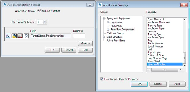
Change the Number of Subparts to 1 single subpart and using the “Select Class Properties” button confirm “Use Target Object’s Property” is active, select Pipe Run Component and set it to the TargetObject.PipeLineNumber that you just created. Click OK and then Close the Block Editor and SAVE the changes to “@Pipe Line Number_3dblock. If you like you can go back to “Edit Annotation” to confirm that the Block Name is set correctly, but trust me – it is. More importantly, Click “Apply” to save your work.
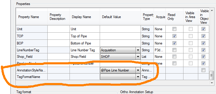
We have one last task in the Project Setup before we move on to a whole new ballgame with our Isometrics. In the Main window locate Annotation Style Name and set it to @Pipe Line Number. Once that is complete you may exit the Project Setup by clicking “OK”.
SETUP THE ISOMETRIC TAG
This part is exactly the same as the previous article so users who have done this have completed all the necessary steps and you are ready to move on to “Implementing These Revisions On Existing Projects”.
For the first timers - now comes the tricky part. Out of the box the Isometrics will only include three items: Line Number, Size and Spec. I can make it rearrange the sequence of these to a degree, but I can never make it put the Line Number between the Size and the Spec, nor can I make it include the Service in the sequence at all. However, I can use the Pipe Line Number property we created earlier.
Basically you need to edit a couple of files that the Isometric generator uses. Assuming you have not changed the location in your Project Setup, using Windows Explorer, locate within you’re project the folder Isometric. There you should see several folders like “Check_ANSI-B” and “Final_ANSI-C”. Each of these folders contain the two files we must edit so you will need to edit each type of Isometric you would like this change to occur in. Enter the folder of your desire and you will find the two files we need: Iso.atr and IsoConfig.xml
Starting with Iso.atr – open it with Notepad. Go down to the very bottom of the file and under BOM-ATTRIBUTES enter a new line that reads as: PipeRunComponent.PipeLineNumber

Save and Exit the file.
Now with Notepad, open the file IsoConfig.xml. Double clicking this file will open it in IE, so right click and use Open With Notepad. This is a much larger file, so I would suggest that you use Notepads “Find” function either by CTRL-F or under the Edit menu select “Find”. Either way you are looking for LineNumberScheme Name and there is a space before Name. This term is only used once in the entire file.
Scroll down a little and change these three setting as follows:
Format="{1}" ComponentFields="Size PipeLineNumber” ComponentFormat="{1}"

Save and Exit the file.
CONCLUSION
Create and annotate a P&ID, route some piping in Plant 3D by line number, create and annotate an Ortho and an Iso of the line and the results should be as follows:
P&ID Line Number
Pipe Routing Line Numbers 
Pipe Tool Tip 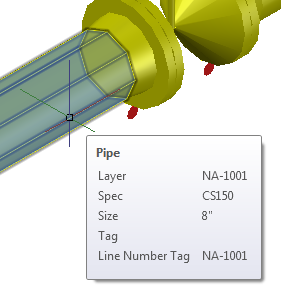
Ortho Line Number 
Isometric Line Number 
A couple of side notes and additional benefits. Note that the Pipe Routing Line Numbers from the P&ID’s now carries the Service with it making it easier to sort and manage. This should also translate over to your Layer names.
Also, when you were annotating your Ortho, your new @Pipe Line Number should have been the default annotation style so press ENTER and don’t stop for anything!

IMPLEMENTING THESE REVISIONS ON EXISTING PROJECTS
As stated previously, this section is only for those users who implemented the original article.
The first thing you must do is delete the original Pipe Line Number Tag format we created. Back in the Project Setup dialog box tree on the left, expand and select the following:
Plant 3D DWG Settings > Plant 3D Class Definitions > Piping and Equipment > Pipe Run Component
Using the slide bar in the Properties section go all the way to the bottom of the Properties where you will find TagFormatName set to Pipe Line Number. Using the drop down box you need to set this to nada, nothing, zilch, just blank it out!
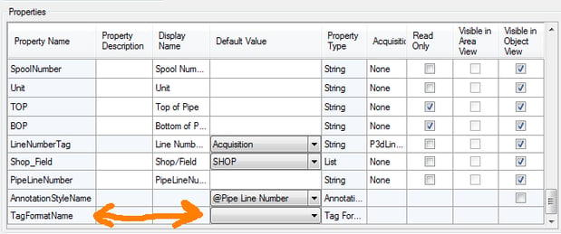
Next, hit Apply to set this value. Then and only then can you select the Tag format named Pipe Line Number and Delete it. Then select OK and exit out.
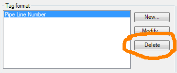
Technically you did not have to delete the tag format, but if anyone ever accidently reset the TagFormatName back to it your validations will no longer work. So avoid that accident and don’t ever add a tag format back to your Pipe Run Component again.
Now if your project does not contain any 3D Piping whatsoever such as a Template Project – you are done. But If you have already modeled piping then you have one more process to complete. You see the Tag still exists on any piping it has been applied to so you need to remove the tag from all of your existing piping and there is only one way to do that and that is with the Data Manager and Excel.
Open the Data Manager and set it to “Plant 3D Project Data”. Under Piping and Equipment right click on Pipe Run Component and select Export.
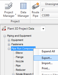
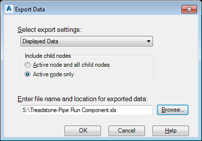
In the Export Data dialog box, set it to Active node only and browse to a location where you can find the file but leave the file name itself as is.
Now locate the file and open it in Microsoft Excel. Locate the Column labeled Tag. It should be around Column AI. Unfortunately, due to sheet protection you cannot sort by this column and you do not want to delete everything in this column. Pipe Run Components such as Valves, Instrumentation, Supports, etc. actually do have Tags and you need not touch those. However, anything that looks like your pipe line number tag needs to be blanked out. You should be able to recognize these tags fairly easily but still pay attention.
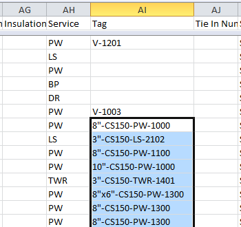
Note that I am leaving the Valve Tags and only deleting the piping and reducer tags in this image. Once you have deleted all the appropriate tags, save and exit Excel.
Back in the Data Manager and the Plant 3D Project Data, right click once again on Pipe Run Component and select Import. If you get the log file message click OK but then browse and Open the Excel file you just modified. In the Import Data dialogue box select OK.
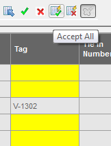
In the Data Manager every line that has been changed is highlighted in yellow so we must accept these changes in order for them to be implemented. Finish this out by selecting the “Accept All” button.
Save your drawing and you can now Validate your Project and no longer have all those pipe line mismatches.
As stated at the beginning of this article, this has to be done on each and every project – both the REVISED sections in the main article and this last section. If you can live with the validation errors on your existing projects you can leave them as is but if you use one of these existing projects as a template for creating a new project then you will carry the validation errors into the new project unless you update the new project with these revisions.



Comments