Who would have thought that AutoCAD Electrical is a “family” of sorts? Part of the power of AutoCAD Electrical is the ability to tie together various symbols that represent one component. Think of a relay. You have the coil and associated contacts shown on multiple pages of your schematic package. That is a perfect example of parent/child symbols.
So, how is AutoCAD Electrical allow for "families." Besides Parent/Child relationships, you can tie any symbols together with "Sibling" symbols. Examples include a switch in a P&ID drawing to an input on a PLC. Others include hydraulics, pneumatics, single line diagrams, wiring diagrams, etc. If symbols are represented in multiple drawings, you can set them up to be tied together.
Why? To save you a bunch of work, both in the design and build/debug phases. A proximity switch shown on a PLC is also placed on a fluid power schematic. They are, in reality, one component with the same device ID (typically) and should be counted once in the BoM.
A few examples might be part of your current designs.
Example: Proximity Switches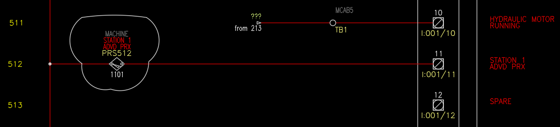
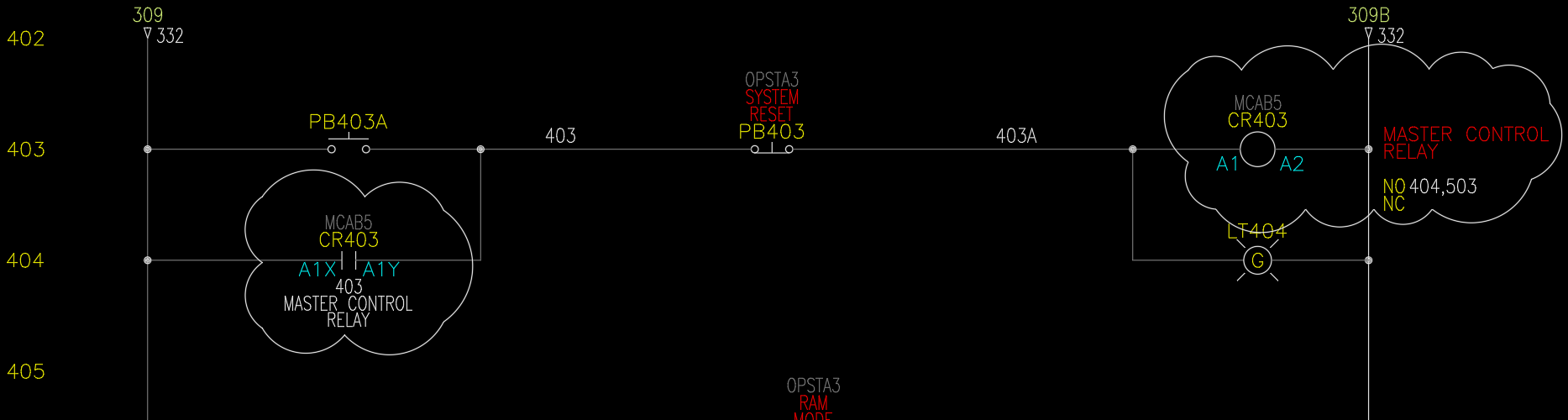
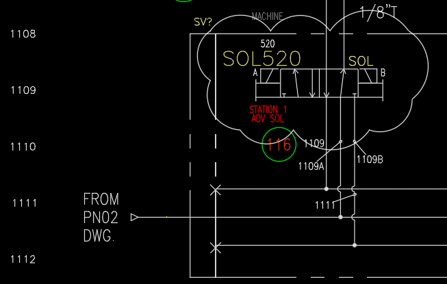
Parent Symbol – I/O Schematic
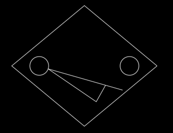
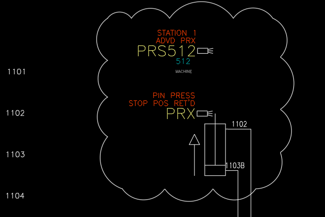 Child Symbol – Pneumatic Schematic
Example: Solenoid
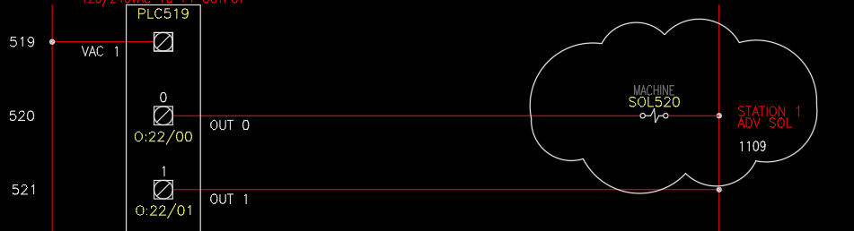
Parent Symbol – I/O Schematic
Child Symbol – Pneumatic Schematic
Are you getting the idea? Make a change to one, and the other will update. But how do you set these symbols up? Some are set up for you "out of the box." Coils and contacts, for example.
Here is a quick guide to creating the relationship between “Parent/Child” or “Sibling” symbols.
Parent Symbol
- Create the graphics for the parent symbol
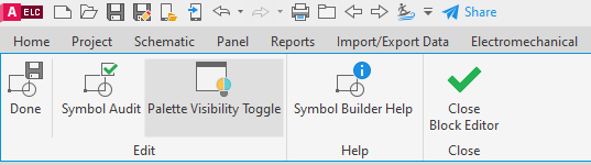
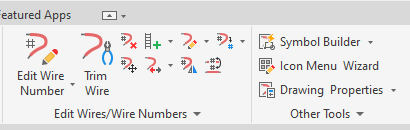
- From the Schematic Tab, go to the Symbol Builder command.

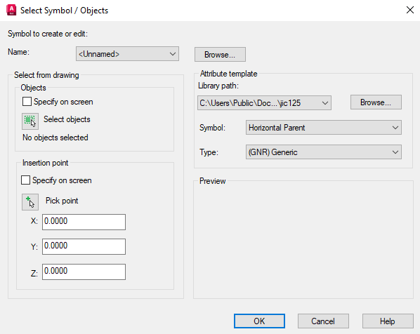
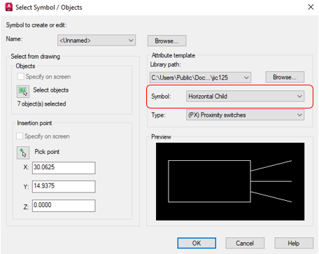
- After selecting objects and picking an insertion point, be sure to choose a PARENT category and then select OK.
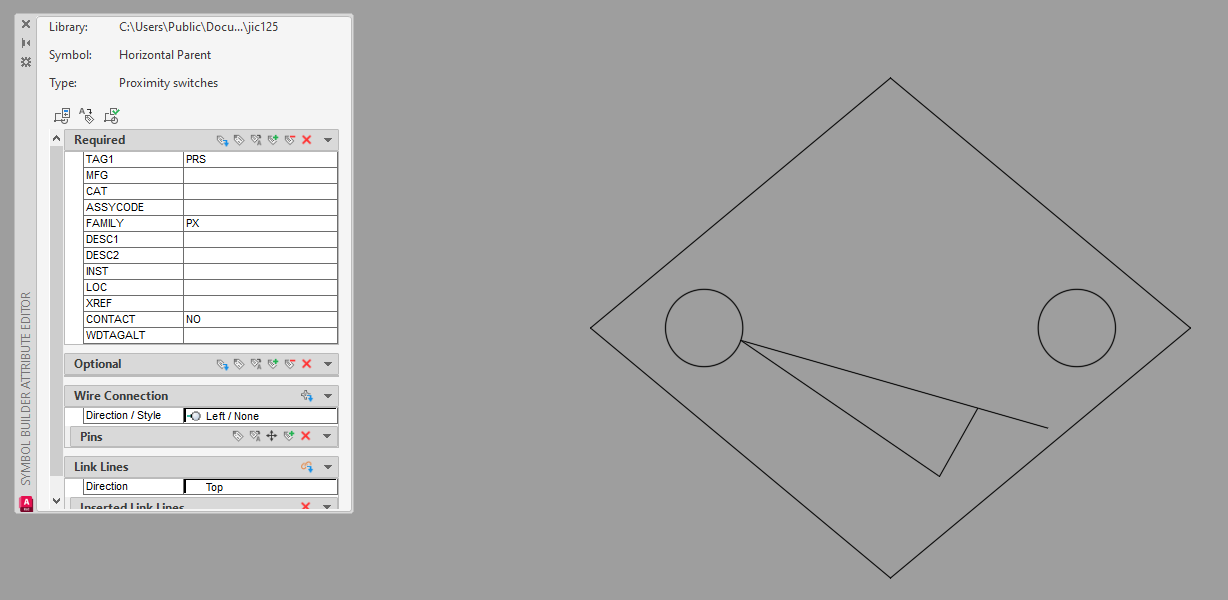
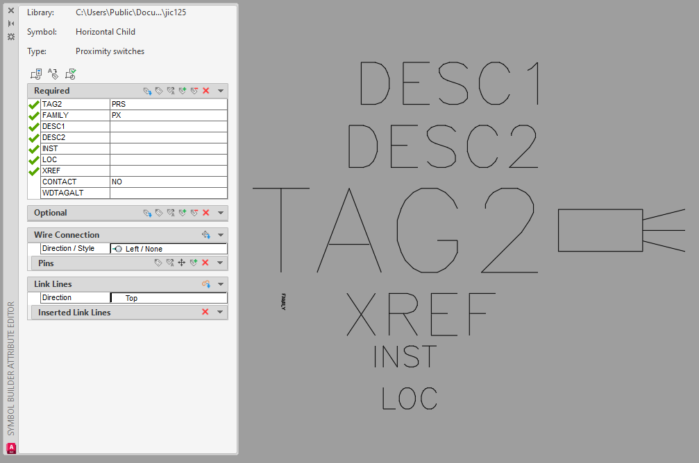
- Add the required attributes.
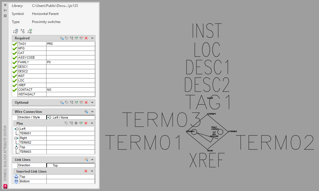
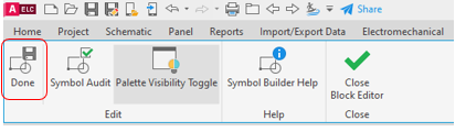
- Select “Done” from the Symbol Builder
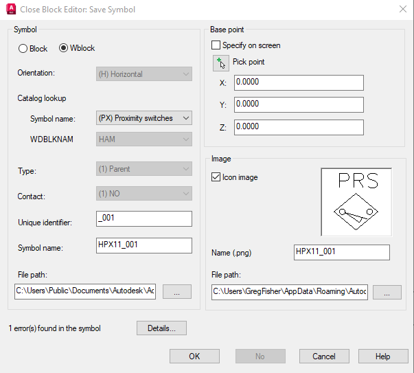
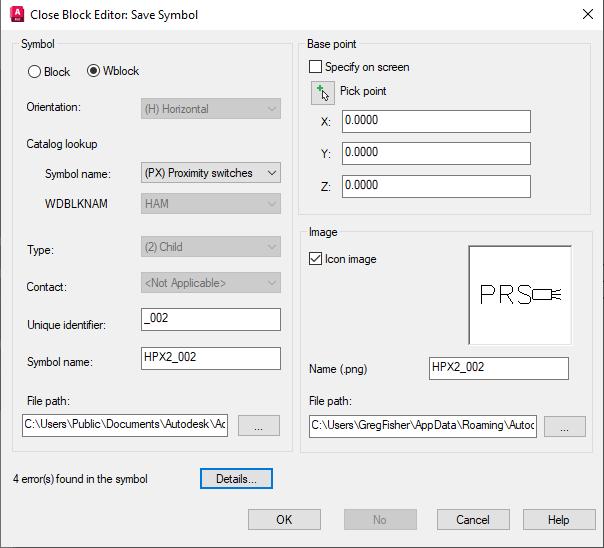
- Then select a path pointing to your custom library/folder for the block and image file.
- Then select a path pointing to your custom library/folder for the block and image file.
Child Symbol
- Create the graphics for the child symbol
- From the Schematic Tab, go to the Symbol Builder command.
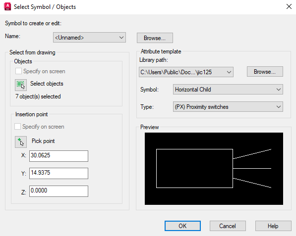
- After selecting objects and picking an insertion point, be sure to choose a CHILD category and then select OK.
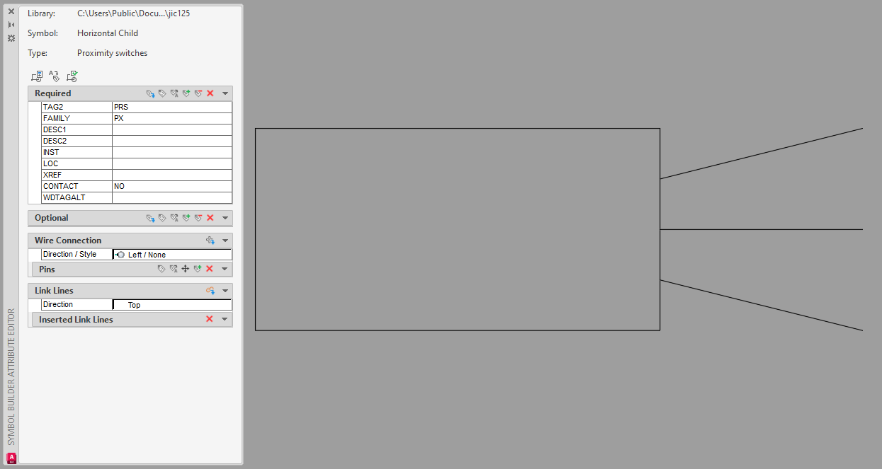
- Add your required attributes.
- Then select Done from the Symbol Builder tab.
- Select a path pointing to your custom library/folder for the block and image file.
Your symbols are now set up to be able to link to each other, which will carry Device ID, BoM information and will allow you to show cross-references. Through those cross-references, you can "surf" between components.
Once you start thinking of the various scenarios that can assist you in showing the same component in multiple drawings, you will find more and more uses for the “family” relationships in AutoCAD Electrical.
|
|


Comments