This is the second of two installments on AutoCAD Electrical Pin Lists.
AutoCAD® Electrical tracks the assigned contacts for devices using a combination of Pin Lists fields in the catalog database Pin Lists tables. These Pin Lists tables contain four fields named COILPINS, PINLIST, PEERCOILPINS and PEERPINLIST. In the previous installment (Part One) of “The Pin Is Mightier Than The Coil” we concentrated on the COILPINS and PINLIST fields, but now it is time to delve deeper into the two “PEER” fields.
PEERCOILPINS & PEERPINLIST
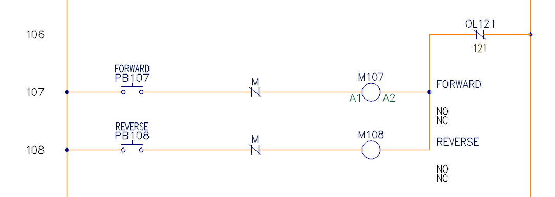
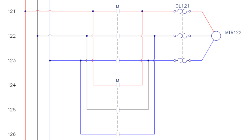
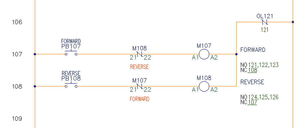
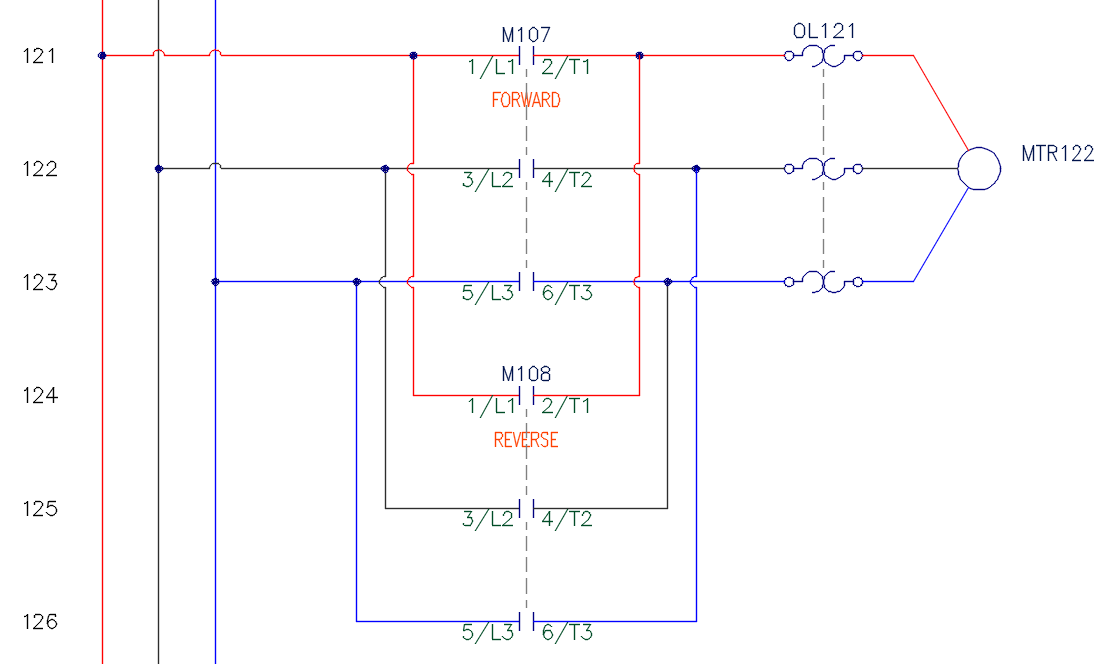
PEER fields are used when two parent components need to share pin information, such as in a reversing motor. For this we will take a look at an out-of-the-box example. Here is a simplified schematic of both the single phase and three phase that we will be using.
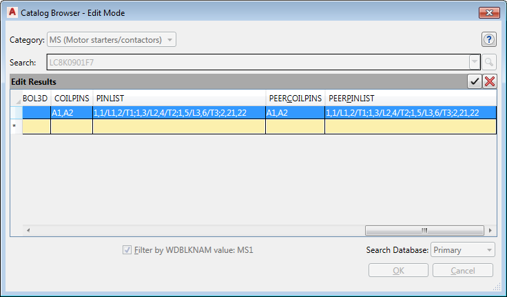
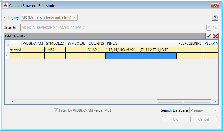
On the single phase, use Edit Component on the forward Motor Starter (M107) and select Lookup. Next in the “Catalog Browser” dialog box, search for LC8K0901F7 so that we can limit our result to just the one motor starter that we will be looking at as seen in the image below.
In the upper right hand corner of the dialog box, edit the catalog database by selecting the pencil icon.  Using the slider bar move all the way to the right so that you can see the four columns named COILPINS, PINLIST, PEERCOILPINS and PEERPINLIST just like before. However this time all the fields contain data.
As seen in our schematic above, a reversing motor starter can include two parent contactor coils, M107 for forward and M108 for reverse. The parent coil (M107) has its own pin list, COILPINS and PINLIST, but the second parent coil utilizing the same part data uses PEERCOILPINS and PEERPINLIST. The PEERCOILPINS field is for the second parent component and the PEERPINLIST field is for the second child components.
Also, just like the COILPINS and PINLIST in the first installment (Part One), both the PEERCOILPINS and the PEERPINLISTS fields use the exact same format:
TYPE,TERM01,TERM02,TERM03,etc; TYPE,TERM01,TERM02,TERM03,etc
As well as the exact same Type Codes:
| PEERCOILPINS | PEERPINLISTS | ||
|
Undefined = 0 Normally Open = 1 Normally Closed = 2 |
Normally Open = 1 Normally Closed =2 Form-C = 3 Convertible = 0 Undefined = 4 Stacked Terminal = 5 |
In this particular instance PEERCOILPINS is identical to COILPINS and PEERPINLIST is identical to PINLIST but they are not necessarily always identical. For instance in some cases the first parent coil may have a NO auxiliary contact but the second parent coil has a NC auxiliary contact based on the specifications of the manufacturer. In either case, both “PEER” fields are setup and work exactly the same as the two fields we covered in detail in the first installment (Part One). Go ahead and exit out of edit mode and in the Catalog Browser select this TELEMECANIQUE LC8K0901F7 starter coil so we can see how this all works together in our schematic.
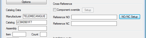
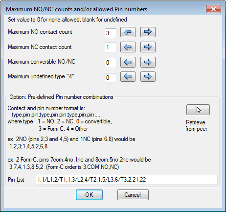
Before we return to the drawing let’s take a quick look at the NO/NC Setup, under Cross-Reference by selecting that button back in the “Insert / Edit Component” dialog box.
Remember the COILPINS field was used to populate the pins in the previous dialog box, but here we can see the data pulled from the PINLIST field. Using this data the software was able to calculate the number of NO, NC, convertible and undefined contacts available for this part. This data is used for the error checking. At the bottom you see the Pin List data exactly as it was entered in the PINLIST field and this data is used to provide the pins for the child components in the sequence it is listed.
Select OK and OK to return to the drawing.
Now use Edit Component on the reversing Motor Starter (M108). So that my BOM’s will be correct I do not want to assign manufacturer and catalog data to this coil. Instead I want to set it up as a “Peer” to the first coil. To do this, select the NO/NC Setup button again. Since we did not assign any catalog data this time, everything in the dialog box is blank. Midway down the dialog box on the right hand side select Retrieve from peer and select the forward Motor Starter (M107). You are immediately returned to the “Insert / Edit Component” dialog box and the Pins have been set per the PEERCOILPINS field of the forward motor. Also, everything in the NO/NC Setup has been populated but go ahead and click on it to see for yourself if you like. In doing so you will see everything has indeed been populated but this time from the PEERPINLIST of the forward Motor Starter.
Once you complete connecting all the Child Contacts with the parents and all the pins have been automatically assigned based on these Pin Lists tables, your drawing should look like this:
THE FINAL SEQUENCE
One last thing before we complete this discussion on Pin Lists. When you are connecting a Child Component to a Parent that has multiple pins of the same type; if you find in the “Insert / Edit Child Component” dialog box that you are constantly having to select List because it put the incorrect Pin data in the device, this is most likely because the sequence of the pin data may not be in the same sequence that you draw.
For instance, I normally draw my single phase first and then my 3 phase later. As a result I connect up my auxiliary contact to the motor starter first, but in many of the out-of-the-box Pin Lists they have the auxiliary contact listed last in the list. If they are all NO contacts the software will assign the next available, which is most likely L1 and T1. The easy fix is to change the sequence in the catalog as I have done in the image below.
Original PINLIST: 1,L1,T1;1,L2,T2;1,L3,T3; 1,13,14,*NO AUX
Edited PINLIST: 1,13,14,*NO AUX;1,L1,T1;1,L2,T2;1,L3,T3
From now on I save myself and everyone else in my company a few steps every time I assign that particular catalog item. So while in the real world that coil is doing all the work for that motor. In AutoCAD Electrical, the Pin is Mightier than the Coil.

Comments